


. A complete Parts List is available at www.HobartWelders.com
OM-926 Page 24
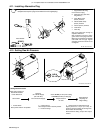
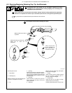
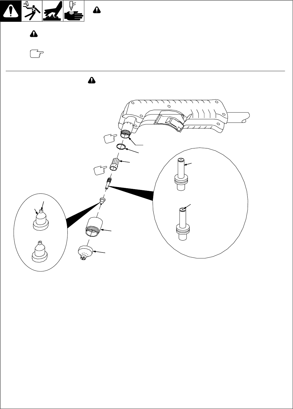
6-3. Checking/Replacing Retaining Cup, Tip, And Electrode
Overtightening will strip threads. Do not overtighten retaining cup during
assembly. Do not cross-thread parts causing stripping. Use care during torch
assembly and parts replacement.
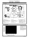
Inspect shield cup, tip, and electrode for wear before cutting or whenever cutting speed has been significantly
reduced. Do not operate torch without a tip or electrode in place. Be sure to use genuine replacement parts.
A good practice is to replace both the tip and electrode at the same time.
Turn Off power source before checking torch parts.
Make sure this area is clean of
any debris.
Make sure swirl ring is clean of any
debris and no holes are
obstructed.
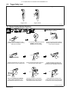
New
Worn
4
3
8
7
6
2
1
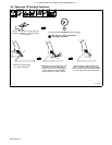
Turn Off power source.
1 Drag Shield
2 Retaining Cup
Remove retaining cup. Check retaining cup
for cracks, and replace if necessary.
3Tip
4 Opening
Remove tip. Check tip, and replace if open-
ing is deformed or 50% oversize. If inside of
tip is not clean and bright, clean with steel
wool. Be sure to remove any pieces of steel
wool afterwards.
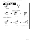
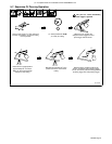
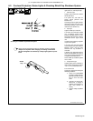
5 Electrode
Check electrode. If center has a pit more
than a 1/32 in (0.8 mm) deep, remove and
replace electrode.
6 Swirl Ring
Remove swirl ring. Check ring, and replace
if side holes are plugged.
7 O-Ring
Check O-rings on torch. If needed, coat with
thin film of silicone lubricant (part no.
169 231). Replace if damaged.
8 Plunger Area
Check this area for any debris or foreign
material. Clean out if necessary.
Carefully reassemble parts in reverse order.
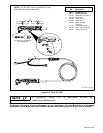
Ref. 803 224
New
Worn
5
1/32 in (1 mm) to 1/16 in
(2 mm) maximum pit
depth depending on
acceptable cut quality