


OM-184 693 Page 7
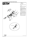
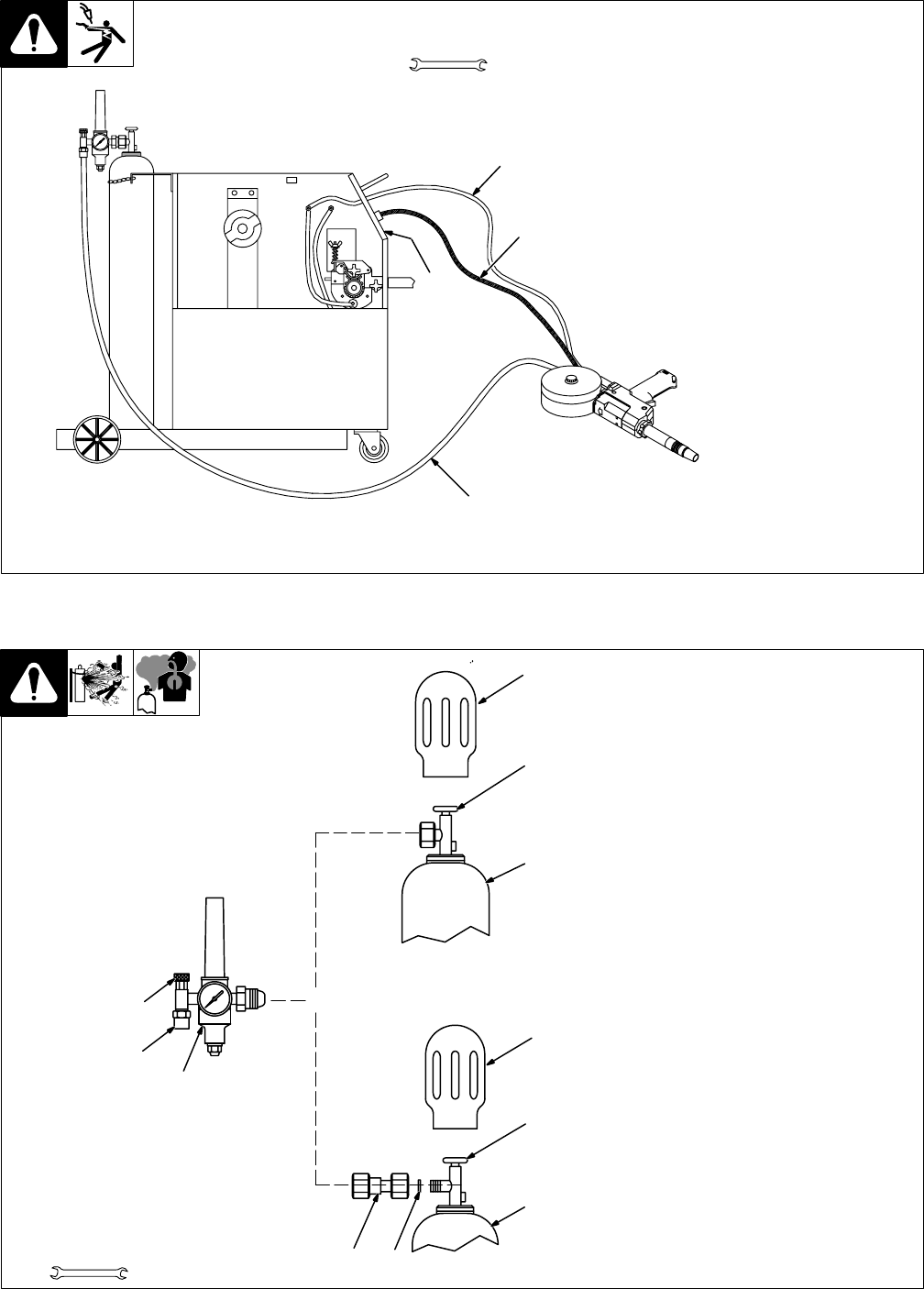
2-6. Connecting To BETA-MIG 251 Welding Power Source
801 758-A
1 Spool Gun Control Module
See BETA-MIG 251 Owner’s
Manual for spool gun control
module installation instructions.
2 Gas Hose
Connect fitting to regulator/flow-
meter (see Section 2-7).
3 Trigger Control Cord
Insert plug into receptacle, and
tighten threaded collar.
4 Weld Cable
Connect to positive (+) weld output
terminal on welding power source
according to its Owner’s Manual.
Tools Needed:
1-1/8, 5/8 in
1
2
3
4
+
_
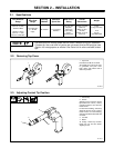
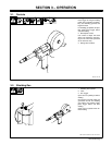
2-7. Installing Gas Supply
ssb3.1* 5/94 – 158 697-A
Obtain gas cylinder and chain to
running gear, wall, or other station-
ary support so cylinder cannot fall
and break off valve.
1 Cap
2 Cylinder Valve
Remove cap, stand to side of
valve, and open valve slightly. Gas
flow blows dust and dirt from valve.
Close valve.
3 Cylinder
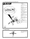
4 Regulator/Flowmeter
Install so face is vertical.
5 Gas Hose Connection
Fitting has 5/8-18 right-hand
threads.
6 Flow Adjust
Typical flow rate is 20 cfh (cubic
feet per hour). Check wire man-
ufacturer’s recommended flow
rate.
Make sure flow adjust is closed
when opening cylinder to avoid
damage to the flowmeter.
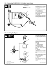
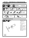
7CO
2
Adapter
8 O-Ring
Install adapter with O-ring between
regulator/flowmeter and CO
2
cylinder.
Tools Needed:
1-1/8, 5/8 in
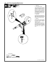
CO
2
Gas
7
8
3
1
2
4
5
6
1
2
3
Argon Gas
OR