OM-198 683 Page 9
SECTION 2 – INSTALLATION
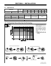
2-1. Specifications
Max. Open- Amps Input at Rated Output, 50 or 60 Hz, Single-Phase
Rated Output
Circuit
Voltage
200 (208) V 230 V 400 V 460 V 575 V KVA KW
250 A at 28 VDC,
40% Duty Cycle
200 A at 28 VDC,
60% Duty Cycle
38 48
2.3*
42
2*
24
1.2*
21
1*
17
0.8*
9.8
0.46*
7.5
0.13*
Wire Type and Diameter Wire Feed Speed Dimensions Net Weight
Solid Steel Stainless Steel Flux Cored 25–700 IPM H: 37 in (940 mm) 212 lb
.023 – .045 in
(0.6 – 1.2 mm)
.023 – .035 in
(0.6 – 0.9 mm)
.030 – .045 in
(0.8 – 1.2 mm)
(.65–17.8 m/min) W: 19 in (483 mm)
D: 30-1/4 in (768 mm)
(96 kg)
* While idling
Operating Temperature Range – –20C to +40C Storage Temperature Range – -30C to + 50C
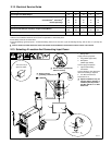
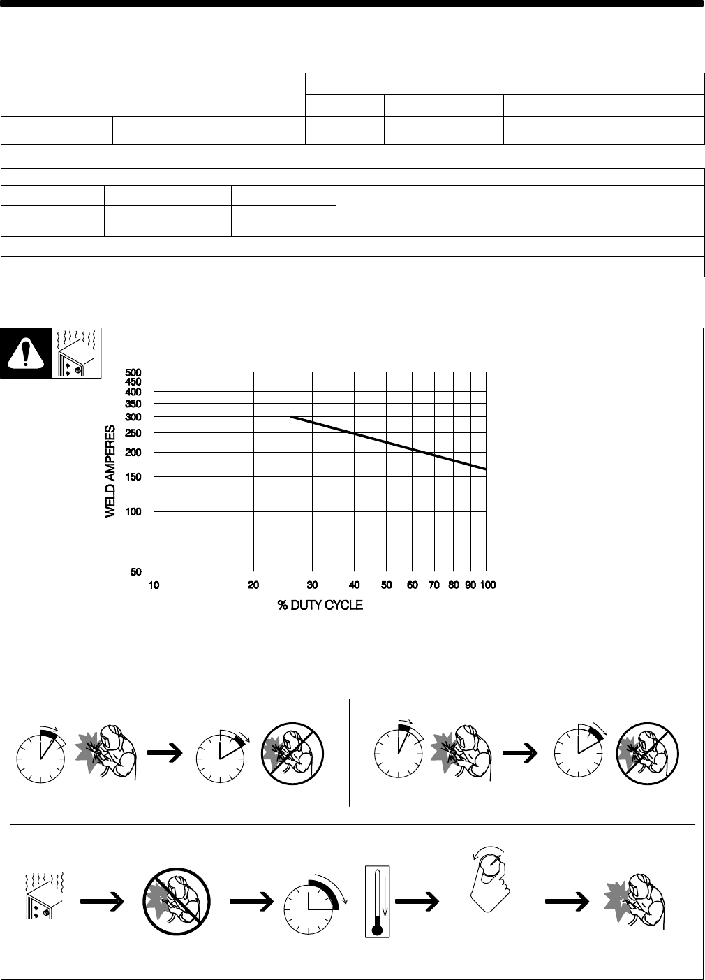
2-2. Welding Power Source Duty Cycle And Overheating
4 Minutes Welding 6 Minutes Resting
6 Minutes Welding 4 Minutes Resting
Duty Cycle is percentage of 10 min-
utes that unit can weld at rated load
without overheating.
If unit overheats, thermostat(s)
opens, output stops, and cooling
fan runs. Wait fifteen minutes for
unit to cool. Reduce amperage or
voltage, or duty cycle before
welding.
Y Exceeding duty cycle can
damage unit and void
warranty.
Overheating
0
15
A or V
OR
Reduce Duty Cycle
Minutes
duty1 4/95 – 150 215-A
40% Duty Cycle At 250 Amperes
60% Duty Cycle At 200 Amperes


