


OM-198 683 Page 14
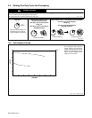
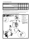
2-12. Electrical Service Guide
Input Voltage 200 230 400 460 575
Input Amperes At Rated Output 48 42 24 21 17
Max Recommended Standard Fuse Or Circuit Breaker Rating In Amperes
Circuit Breaker
1
, Time-Delay
2
60 50 30 25 20
Normal Operating
3
70 60 35 30 25
Min Input Conductor Size In AWG/Kcmil 8 8 12 12 14
Max Recommended Input Conductor Length In Feet (Meters)
96
(29)
127
(39)
156
(47)
206
(63)
209
(64)
Min Grounding Conductor Size In AWG/Kcmil 8 10 12 12 14
Reference: 1999 National Electrical Code (NEC)
1 Choose a circuit breaker with time-current curves comparable to a Time Delay Fuse.
2 “Time-Delay” fuses are UL class “RK5” .
3 “Normal Operating” (general purpose – no intentional delay) fuses are UL class “K5” (up to and including 60 amp), and UL class “H” ( 65 amp and
above).
Y Caution: Failure to follow these fuse and circuit breaker recommendations could create an electric shock or fire hazard.
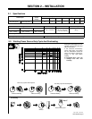
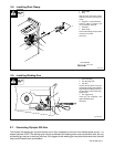
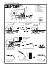
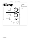
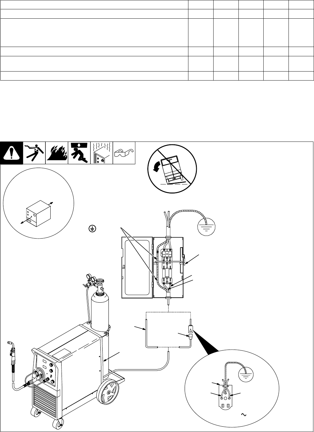
2-13. Selecting A Location And Connecting Input Power
1 Rating Label
Supply correct input power.
2 Plug (NEMA Type 6-50P)
3 Receptacle
(NEMA Type 6-50R)
Connect plug to receptacle.
4 Input And Grounding
Conductors
Connect directly to line disconnect
device if hard wiring is required.
5 Line Disconnect Device
See Section 2-12.
Y Special installation may be
required where gasoline or
volatile liquids are present –
see NEC Article 511 or CEC
Section 20.
802 477
L1L2
230 VAC, 1
18 in (457 mm) of
space for airflow
L1
L2
Y Do not move or operate unit
where it could tip.
Y Always connect
grounding conductor first.
= GND/PE
3
2
5
1
4