


OM-314 Page 11
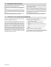
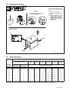
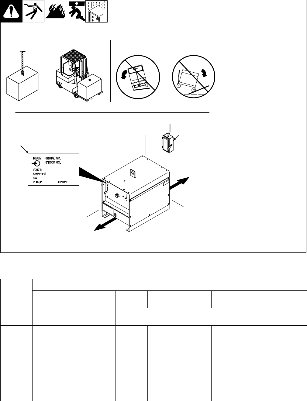
2-5. Selecting A Location
1 Rating Label
Use rating label to determine input
power needs. Label located on front
panel.
2 Line Disconnect Device
Locate unit near correct input pow-
er supply.
Y Special installation may be
required where gasoline or
volatile liquids are present –
see NEC Article 511 or CEC
Section 20.
2
18 in
(460 mm)
18 in
(460 mm)
Movement
Location And Airflow
1
Y Do not move or operate unit
where it could tip.
Tipping
loc_1 3/96 / Ref. ST-111 900-D
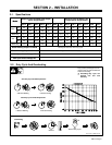
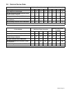
2-6. Weld Cable Sizes
Total Cable (Copper) Length In Weld Circuit Not Exceeding
100 ft (30 m) Or Less
150 ft
(45 m)
200 ft
(60 m)
250 ft
(70 m)
300 ft
(90 m)
350 ft
(105 m)
400 ft
(120 m)
Welding
Amperes
10 To 60%
Duty Cycle
60 Thru 100%
Duty Cycle
10 Thru 100% Duty Cycle
100 4 4 4 3 2 1 1/0 1/0
150 3 3 2 1 1/0 2/0 3/0 3/0
200 3 2 1 1/0 2/0 3/0 4/0 4/0
250 2 1 1/0 2/0 3/0 4/0 2-2/0 2-2/0
300 1 1/0 2/0 3/0 4/0 2-2/0 2-3/0 2-3/0
350 1/0 2/0 3/0 4/0 2-2/0 2-3/0 2-3/0 2-4/0
400 1/0 2/0 3/0 4/0 2-2/0 2-3/0 2-4/0 2-4/0
*Weld cable size (AWG) is based on either a 4 volts or less drop or a current density of at least 300 circular mils per ampere. S-0007-D