OM-314 Page 14
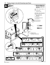
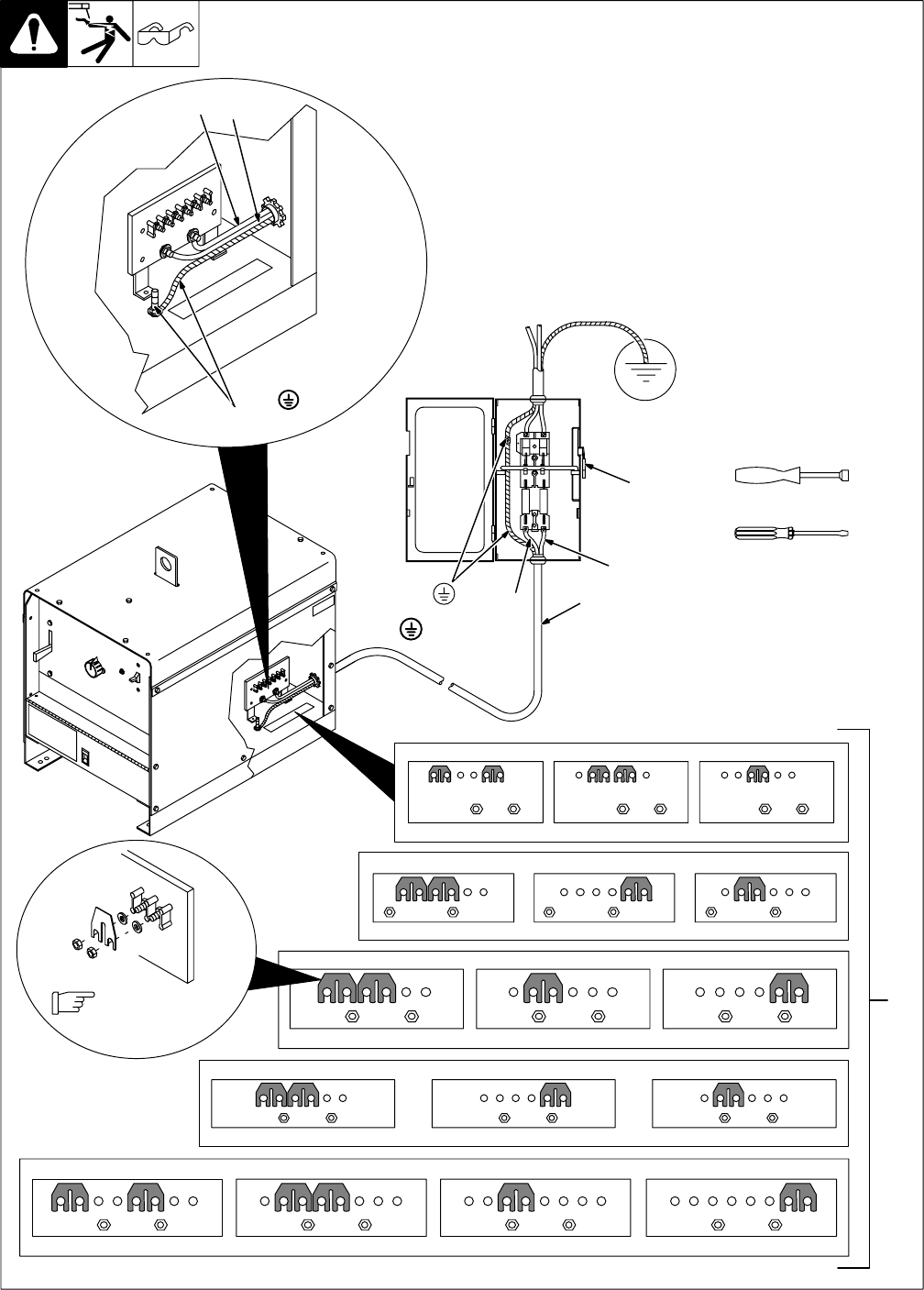
2-9. Placing Jumper Links And Connecting Input Power
input_3 3/96 - ST-111 901-F
Y Have only qualified persons
make this installation. See
rating label in Section 2-5,
and be sure to supply correct
input power.
Check input voltage available at
site.
Remove side panel.
1 Jumper Link Label
Check label – only one is on unit.
Move jumper links to match input
voltage, and label on unit.
2 Input And Grounding
Conductors
See Section 2-8.
3 Line Disconnect Device
See Section 2-8.
Connect input power.
Reinstall side panel.
L1
L2
3/8, 7/16, 1/2 in
208 VOLTS
S-035 209-A
LL
230 VOLTS
LL
460 VOLTS
LL
575 VOLTS
LL
230 VOLTS
LL
460 VOLTS
LL
S-010 587-B
575 VOLTS
LL
1
230 VOLTS 460 VOLTS200 VOLTS
S-083 566-C
LL LL LL
S-047 672-A
2
S-021 145-B
220 VOLTS
LL
380 VOLTS
LL
440 VOLTS
LL
260 VOLTS
LL
380 VOLTS
LL
520 VOLTS
LL
Do not overtighten.
3
Y Always connect
grounding conductor first.
= GND/PE
L1
L2
GND/PE


