page 60 008-0608-00
10.2 Wiring
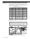
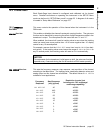
Connect the transducer to a Strain-Gage Input channel by wiring it to the 12-pin con-
nector of that channel. The Customer Information Sheet that shipped with the instru-
ment describes which cards are installed in each channel. The pin-out for this
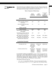
connector is shown on the following table.
The Analog Output and Analog Return pins are electrically isolated from all other pins
on the instrument.
The maximum recommended cable length to a Signature Module is 100 feet [30m].
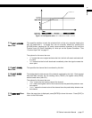
Figure 10-1: Unamplified Transducer Connection to Strain-Gage Input Channel
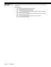
Table 4-3: Strain-Gage Input Channel Pin Connections
Pin Label Function Reference Pin
1 (top) +EXC (+)Excitation 10
2 +SEN (+)Sense 10
3-SEN (-)Sense 10
4 -EXC (-)Excitation 10
5 +SIG (+)Signal 10
6 -SIG (-)Signal 10
7 +OUT Analog Output 8
8 -OUT Analog Return -
9 +MEM (+)Signature 10
10 -MEM (-)Signature / Digital Ground -
11 AUX1 Auxiliary Function 1
(connect to pin 10 to activate)
10
12
(bottom)
AUX2 Auxiliary Function 2
(connect to pin 10 to activate)
10
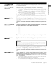
NOTICE
If you are not using remote sensing of excitation, jumper (+)Sense to (+)Excita-
tion and (-)Sense to (-)Excitation. If nothing is connected to (+)Sense and (-
)Sense, the instrument will enter the ERROR mode with error code 46.


