


mínimas
de trabajo
de 10,34
bar. Use
mangueras
de aire de
1/2” si la longitud de las mismas es
de 15m ó más. Para un mejor
rendimiento, instálele a la her-
ramienta un conector rápido de
9,5mm(3/8”) (roscas de 6,4mm (1/4”)
NPT) cuyo diámetro interno sea de
0,315" (8mm) y un acoplador rápido
de 9,5mm(3/8”) a la manguera de
aire.
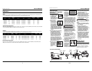
4. Use un regulador
de presión (de 0
bar-8,27 bar) en el
compresor. Se
necesita un regu-
la-
dor de presión para controlar la pre-
sión de operación de la herramienta
entre 4,14 bar y 6,90 bar.
MODO DE OPERACIÓN
Siempre
cer-
ciórese de saber en que modo va a
operar la clavadora antes de comenzar
a usarla. De lo contrario, le podría oca-
sionar la muerte o heridas graves.
MODO DE SECUENCIA SINGULAR
Este sistema
requiere que
oprima el gatillo
cada vez que vaya
a clavar un sujeta-
dor. Para clavar el elemento de contac-
to debe tocar la superficie de trabajo y
el operador debe oprimir el gatillo.
Debe soltar el gatillo antes de clavar
otro sujetador.
CÓMO USAR LA HERRAMIENTA DE
DISPARO SECUENCIAL
Cheque
el
funcionamiento del mecanismo del
elemento de contacto antes de cada
uso. El elemento de contacto se debe
desplazar libremente, sin pegarse, a lo
largo del área de desplazamiento. El
resorte del elemento de contacto debe
regresar el elemento de contacto a su
posición original totalmente extendido.
No use la herramienta si el mecanismo
del elemento de contacto no está fun-
cionando adecudamente. Podría oca-
sionarle heridas.
1. Desconecte la
herramienta de
la fuente de
suministro de
aire.
!
PRECAUCION
!
ADVERTENCIA
Cómo usar la
Herramienta (Cont.)
La super
ficie de
trabajo se podría dañar debido a la
lubricación excesiva. La lubricación
adecuada es la responsabilidad del
propietario. Si no lubrica la herramien-
ta adecuadamente, ésta se dañará rápi-
damente y la garantía se cancelaría
1. Desconecte la
herramienta
de la fuente de
suministro de
aire para lubri-
carla.
2. Gire la herramienta
de modo que la
entrada de aire
quede mirando hacia
arriba. Agregue de 4
a 5 gotas de aceite no
detergente 30W en la entrada de
aire. No use aceites detergentes,
aditivos de aceite, ni aceites para
herramientas neumáticas. Los
aceites para herramientas neumáti-
cas contienen solventes que pueden
averiar los componentes internos de
la herramienta.
3. Después de agre-
gar aceite, haga
funcionar la herra-
mienta breve-
mente. Limpie
todo exceso de
aceite que salga del orificio de sali-
da de aire.
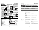
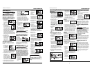
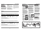
CONEXIÓN RECOMENDADA
La ilustración de abajo le muestra la
conexión recomendada para la herra-
mienta.
1.
El compresor de
aire debe tener
la capacidad de
suministrar un
mínimo de 4,14
bar cuando la
herramienta esté en uso. Si el sumin-
istro de aire es inadecuado podría
haber pérdida de potencia y falta de
consistencia en el funcionamiento.
2. Puede utilizar un lubri-
cador para lubricar la
herramienta.
Igualmente, puede
utilizar un filtro para
remover las impurezas
líquidas y sólidas que
podrían oxidar u obstruir las partes
internas de la herramienta.
3. Use mangueras de aire de 9,5mm
(3/8”) diseñadas para presiones
AVISO
Modelo HDN23200
Manual de Instrucciones
4-Sp
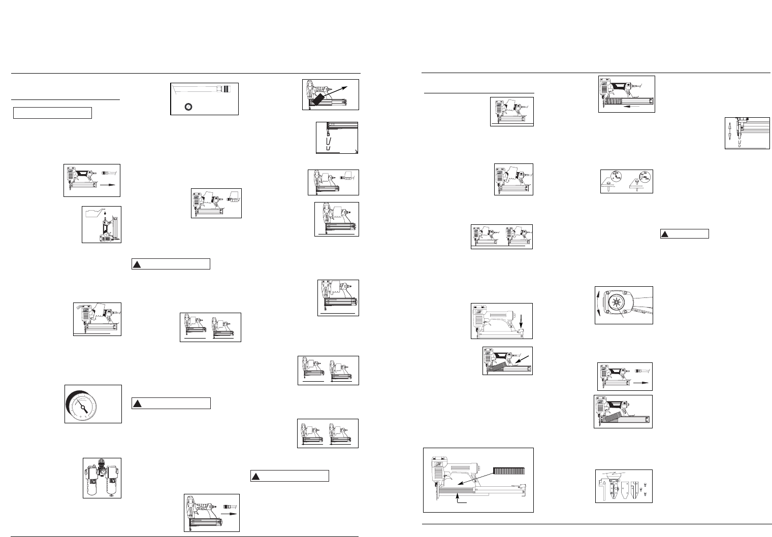
Operating The Tool
(Continued)
5. Depress the Work
Contact Element
(WCE) against the
work surface with-
out pulling the trig-
ger. The tool MUST NOT OPERATE.
Do not use the tool if it operates
without pulling the trigger. Personal
injury may result.
6.
Remove tool from the
work surface. The
Work Contact Element
(WCE) must return to
its original down posi-
tion. Pull the trigger. The tool MUST
NOT OPERATE. Do not use the tool if
it operates. Personal injury may result.
7. Depress the
Work
Contact
Element
(WCE) against the work surface. Pull
the trigger. The tool MUST OPER-
ATE.
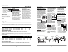
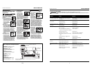
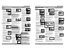
LOADING/UNLOADING THE TOOL
1. Always connect the tool to the air
supply before loading fasteners.
2. Push down
on the latch
button. Pull
back on the
magazine
cover.
3a.For nails, insert a
stick of Campbell
Hausfeld nails or
equivalent (see
"Fasteners" section) into the maga-
zine. Make sure the pointed ends of
the fasteners are resting on the bot-
tom ledge of the magazine when
loading. Make sure the nails are not
dirty or damaged.
3b.For staples, load a clip of staples
with the crowns straddling the mag-
azine rail.
4. Push the maga-
zine cover for-
ward until latch
button pops
up.
5. Always unload all fasteners before
removing tool from service.
Unloading is the reverse of loading,
except always disconnect the air
supply before unloading.
ADJUSTING THE FASTENER PENE-
TRATION
1. Regulate the air
pressure to 60
psi at the tool.
2. Connect the air supply and test for
penetration by driving fasteners
into a sample piece of wood. If the
fasteners do not achieve the desired
penetration, adjust the air pressure
to a higher setting until the desired
penetration is achieved. Do not
exceed 100 psi at the tool or dura-
bility of the tool will be reduced.
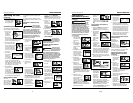
ADJUSTING THE DIRECTION OF THE
EXHAUST
The HDN23200 is
equipped with an
adjustable direc-
tion exhaust
deflector. This is
intended to allow
the user to change the direction of the
exhaust. Simply twist the deflector to
any direction desired.
CLEARING A JAM FROM THE TOOL
1. Disconnect the
air supply from
the tool.
2. Remove all
fasteners
from the
magazine
(see
"Loading/ Unloading The Tool").
Failure to do so will cause the fas-
teners to eject from the front of the
tool when the nose assembly is
removed.
3. Remove (3)
cap screws
from the nose
of the tool.
Remove nose
plate, spacer and Work Contact
Element (WCE) to expose jammed
fastener.
4. Reinstall nose assembly in reverse
order in step #3.
5. Make sure the trig-
ger and Work
Contact Element
(WCE) move freely
up and down with-
out sticking or binding.
Technical Support
Please call our Tool Hotline at 1-800-
543-6400 with any questions regarding
the operation or repair of this tool or
for additional copies of this manual.
Fastener And Replacement
Parts
Use only
genuine Campbell
Hausfeld 18 gauge fasteners (or equiv-
alent - see Fastener Interchange
Information). Tool performance, safety
and durability could be reduced if
improper fasteners are used. When
ordering replacement parts or fasten-
ers, specify by part number.
Tool Repair
Only qualified personnel should repair
the tool, and they should use genuine
Campbell Hausfeld replacement parts
and accessories, or parts and acces-
sories which perform equivalently.
Assembly Procedure For
Seals
When repairing a tool, the internal
parts must be cleaned and lubricated.
Parker O-lube or equivalent must be
used on all o-rings. Each o-ring must be
coated with O-lube before assembling.
A small amount of oil must be used on
all moving surfaces and pivots. After
reassembling, a few drops of 30W non-
detergent oil or equivalent, must be
added through the air line before
testing.
!
WARNING
Model HDN23200
Operating Instructions
5
2. Saque todos los
sujetadores del
cargador (Vea
la Sección
Carga-
Descarga).
3. Cerciórese de que el
gatillo y el elemento
de contacto se mue-
van libremente en
ambos sentidos sin
atascarse o pegarse.
4. Reconecte la her-
ramienta a la
fuente de sumin-
istro de aire.
5. Presione el
Elemento de
Contacto de Trabajo
contra la superficie
de trabajo sin apre-
tar el gatillo. La herramienta NO
DEBE OPERAR. No use la her-
ramienta si opera sin apretar el
gatillo. Se pueden producir lesiones
personales.
6. Remueva la her-
ramienta de la super-
ficie de trabajo. El
Elemento de
Contacto de Trabajo
tiene que volver a su
posición original. La herramienta
NO DEBE OPERAR. No use la her-
ramienta si opera mientras está lev-
antada de la superficie de trabajo.
7. Apriete el
gatillo y pre-
sione el
Elemento de
Contacto de
Trabajo contra la superficie de tra-
bajo. La herramienta NO DEBE hac-
erse funcionar.
8. Presione el
Elemento de
Contacto de
Trabajo con-
tra la superfi-
cie de trabajo. Apriete el gatillo. La
herramienta DEBE OPERAR.
Una
herramienta que funciona de manera
inadecuada no debe usarse. No active
la herramienta a menos que esté
colocada firmemente contra la pieza de
trabajo.
!
ADVERTENCIA
OIL
OIL
4,14 bar
Min.
6,9 bar
Max.
Aceite
1,27 cm diam. int.
10,34 bar WP
Latch
Button
Magazine rail
movement
Rotate
BUILT TO LAST
BUILT TO LAST
BUILT TO LAST
BUILT TO LAST
movemiento
BUILT TO LAST
BUILT TO LAST
BUILT TO LAST
BUILT TO LAST
BUILT TO LAST
1
2
BUILT TO LAST
BUILT TO LAST
1
2