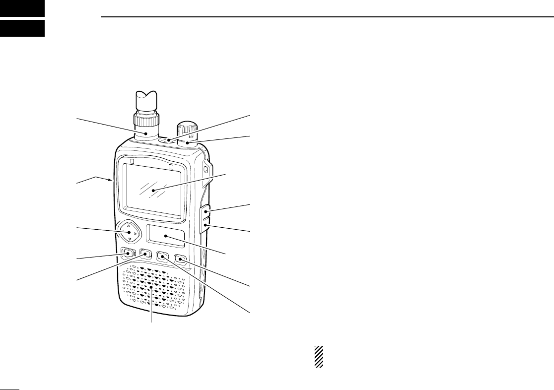
■ Panel description
q ANTENNA CONNECTOR (p. 1)
Connects the supplied antenna.
w FUNCTION SWITCH [FUNC]
While pushing this switch, other switches and tuning dial
perform secondary functions.
•“Push [FUNC] + a switch” means “while pushing the [FUNC]
switch, push the switch” as indicated by the mark e.g.[↕] etc.
e MULTI FUNCTION SWITCH [MULTI]
➥Push [↕] to adjust the audio level. (p. 11)
➥Push [FUNC] + [↕] to toggle between AM TV (frequency
selection), amateur TV (ATV-type) and WFM/FM/AM
modes when the color LCD is OFF. (p. 34)
➥Push [FUNC] + [↕] for 2 sec. to toggle the color LCD ON
and OFF (p. 6, 30 MHz and above only).
➥Push [FUNC] + [↕] to select color LCD function when the
color LCD is ON. (p. 6)
➥Push [↔] to select the operating band (VHF, UHF, etc.)
in VFO mode. (p. 7)
•Broadcast, HF, 50 MHz, FM broadcast, VHF avionics, 144
MHz, 300 MHz, 400 MHz, 800 MHz, 1200 MHz, 2400 MHz
and TV bands (channel selection) can be selected.
➥Push [FUNC] + [↔] to select the dial select step. (p. 39)
➥Push [↔] for 2 sec. to start a scan. (pgs. 19, 20)
➥Push [FUNC] + [↔] for 2 sec. to start a tone scan. (p.
30)
Push [↕] means push ó up or down; and
push [
↔
] means
push ó left or right
.
r POWER SWITCH [POWER]
Push for 2 sec. to toggle the receiver power ON and OFF.
2
2
PANEL DESCRIPTION
q
w
e
r
t
y
u
i
o
Color LCD
(p. 6)
Sub LCD
(p. 4)
SPEAKER
!0
!1


