


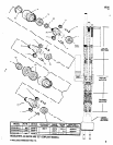
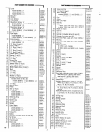

47368-( ) COLLETS
COLLET
BORE
ACCEPTS
COLLET
BORE
ACCEPTS
PART
DIA. DRILL SIZE
PART
DIA. DRILL SIZE
NUMBER
(REF.) INCH NO. MM
NUMBER
(REF.) INCH NO. MM
47368-1 .039
61 1.0
47368-17 .102
38 26
47368-2 .043
57 1.1
47368-18 .106
36 27
47368-3 .047
3/64 56 1.2
47368-19 .110
7/64 35
20
47368-4 .052
55 1.3
47368-20 .114
33 29
47368-5 .055
54 1.4
47368-21 .118
32 30
47368-6 .059
53 1.5
47368-22 .122
31 31
47368-7 .063
1/16 52 1.6
47368-23 .126
1/8
32
47368-8 .067
51 1.7
47366-24 .130
30 33
47368-9 .071
50 1.8
47368-25 .134
29 34
47368-10 .075
48 1.9
47368-26 .136
35
47368-11 .079
5/64 47 2.0
47368-27 .142
9/64 28
36
47368-12 .083
45 2.1
47368-28 .146
26 37
47368-13 .087
44 2.2
47368-29 .150
25 38
47368-14 .091
43 2.3
47368-30 .154
23 39
47368-15 .094
3/32 42 2.4
47368-31 .157
5/32 22
40
47360-16 .098
40 2.5
NOTE: COLLETS ARE NOT FURNISHED WITH DUAL SPINDLE ATTACHMENT - COLLETS MUST BE ORDERED SEPARATELY.
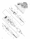
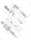
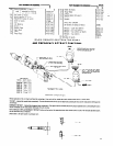
SERVICE KIT NO. 41205-l
SERVICE KIT NO. 41310-1
(FOR SERVICING ONE MODEL 8248-B( )-1, -2, -3 EXCEPT
MODEL 8248-B30-1,
-2, -3 SEE KIT NO. 41310-1)
CITY. PART NO. DESCRIPTION
QTY. PART NO. DESCRIPTION
1 Y65-8
Bearing
2 Y325-2
“0” Ring
1
38232 Bearing
“0”
Y325-7 “0”
Ring
5
32860 Blade
Ring
2
35733 . Spring
2 Y325-12 “0”
Ring
2
35922 Seal
2 Y325-13 “0”
Ring
1
39461 Screen
1 Y325-16 “0”
Ring
1
39466 Cap
2 Y32524 “0”
Ring
1
41795 Motor Oil
1 Y325-26 “0”
Ring
1
41799 Gear Lube
3 34276 “0”
Ring
1
41954 “0” Ring Lube
5 41082 “0”
Ring
1 41534 “0”
Ring
(FOR SERVICING ONE
MODEL 8248-B30-1.
-2, -3)
QTY. PART NO. DESCRIPTION
QTY. PART NO. DESCRIPTION
-i- 32851 Bearing
2 Y325-2
“0” Ring
1 38232 Bearing
1
Y325-3 “0” Ring
5 32860 Blade
2 Y 325-7
“0” Ring
2 35733 Spring
2 Y325-12
“0” Ring
2 35922 Seal
2 Y325-13
“0” Ring
1 39461 Screen
1 Y325-16
“0” Ring
1 39466 Cap
“0” Ring
1 41795 Motor Oil
“0” Ring
1 41799 Gear Lube
3 34276
“0” Ring
1 41954 “0” Ring Lube
5 41082
“0” Ring
1 41534
“0” Ring
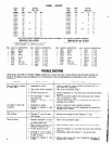
TROUBLE SHOOTING
LISTED BELOW ARE SOME OF THE MOST COMMON CAUSES FOR THE SELF-FEED DRILL TO MALFUNCTION. MALFUNCTIONS BEYOND THE
SCOPE OF THIS MANUAL SHOULD BE BROUGHT TO THE ATTENTION OF YOUR ARO REPRESENTATIVE OR RETURNTHE TOOL TO FACTORY
FOR REPAIR.
CONDITION POSSIBLE CAUSE
Failure to feed or irregular
or erratic feed.
Low speed or motor fails
to operate.
Motor continues to run
after retraction.
Failure to retract.
12
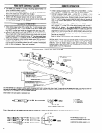
1. Inadequate air supply.
2. Feed control valves improperIy
adjusted.
3. Air leak around cap (12).
4. Dirt or damaged ”O” rings on
spool valve (14).
5. Clogged air passage in valve
housing.
1. Inadequate air supply.
2. Clogged air passage in valve
housing.
1. Piston
not
fully retracted.
2. Damaged “0” ring (11) inside
valve housing.
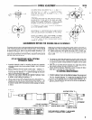
1. Improper adjustment or align-
ment between adjustment screw
and button bleed valve.
2. Feed control valves (23)
Improperly adjusted or dirty.
3. Air leak around cap (12).
4. Damaged “0” rings in muffler
cap, valve housing or spool valve
or seals on piston.
5. Flogged air passage in valve
housing.
CORRECTIVE ACTION
1. Check air supply for correct regulator adjustment (90 p.s.i.g.
max. when tool is operating).
2. Refer to set-up procedure, page 1.
3. Check for damage to ”0” ring. Check and insure caps are properly
tightened.
4. Refer to valve section, page 9, and remove spool valve. Inspect,
clean and replace “0” rings.
5 Remove valve housing from tool. Disassemble and blow all air
passages clear of debris.
1. Check air supply for correct regulator adjustment.
2. Remove valve housing from tool. Disassemble and blow all air
passages clear of debris.
1. Insure piston is not obstructed and is returned all the way back.
2 Remove valve housing from tool. Replace ”0” rings.
1. Refer to set-up procedure, page 1.
2. Check adjustment, refer to page 2. Remove, inspect and clean.
3. Check for damage to ”0” ring. Check and insure caps are properly
tightened.
4. Disassemble, inspect and replace “0” rings and/or seals.
5. Remove valve housing from tool. Disassemble and blow air
passages clear of debris.
PN 49999-070