


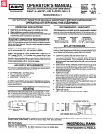

Y--
--Y
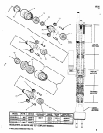
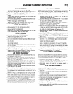
Fig.1
IMPORTANT
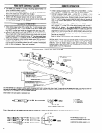
RECOMMENDED METHOD FOR HOLDING DRILLS IN SPINDLES
’
To properly hold drill bit in collet and reduce the chance of slippage,
a flat must be ground on the shank end of the bit. The flat should
be approximately 5/16” (8mm) long and the depth should be 1/3 of
the bit diameter NOTE: If bit
IS
too large to fit into locking insert (smaller
capacity Dual Spindles do not hove insert), a square must be ground
onto the shank end of the bit.
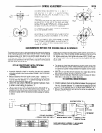
SET-UP PROCEDURE WITH OPTIONAL
HYDRAULIC CHECK
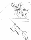
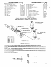
Fsg.4
i ’ b
c‘t NT1 v\
Assemble hydraulic check to mounting bracket and assemble
mounting bracket to tool using washers (Y14-8) and cap screws
(Y154-48).
Measure distance from drill point to work piece - distance “Y”.
Distance “X” between hydraulic check plunger and trip bracket
must be less than distance “Y” to prevent damage to drill point
when it approaches the work piece.
Loosen the cap screws (Y154-48) and position hydraulic check
to obtain correct setting for distance “X”.
Tighten cop screws (Y154-48) securely before operating unit.
Increase the air flow thru the Feed Control Valve marked “F” by
opening two (2) full turns from closed position. This will allow drill
to advance rapidly until the trip bracket contacts plunger of hydraul-
ic check.
Insert bit into spindle and into locking insert (where applicable) In-
suring that one of the set screws locates squarely on the flat of the
bit. Tighten collet firmly, then tighten set screws. NOTE: DO NOT over-
tighten collet. NOTE: Intent of set screws is only to keep bit from turn-
ing in collet.
The Hydraulic Feed Rate Adjustment is located at the name plate
end of the Hydraulic Check Rotate extended spindle until the slot
on spindle IS located midway between the highest and the lowest
settings.
Start drill unit and the drill will advance at a rapid rate until the
trip bracket contacts plunger of hydraulic check.
Slowly rotate the Hydraulic Feed Rate counter clockwise for faster
feed rate or clockwise for slower feed rate.
TO CONTROL BREAKTHROUGH
Position hydraulic check so the distance between the plunger and
the trip bracket (distance “X”) is less than the distance from the
drill point to the opposite side of the work piece (distance “W’).
l
Set-up of the self-feed drill unit will be the same as explained in
Set-Up Procedure, page 1.
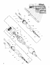
ADJUSTMENT SCREW “6”
7
FEED RATE ADJUSTMENT
* HYDRAULIC CHECK (SEE TABLE)
OUNTING BRACKET 40298
PARTS INDICATED BY ASTERISK (*) ARE INCLUDED
IN 40301-( ) HYDRAULIC CHECK ASSEMBLY.
3