


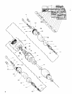
DISASSEMBLY/ASSEMBLY INSTRUCTIONS
M106
21
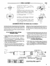
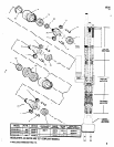
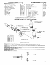
GEARING ASSEMBLY
-Assemble gears to spindle and secure with shafts.
-Align notch at end of shaft with step on spindle (align notch of
shaft with spacer (80) for auxiliary gearing).
-Pack bearing (70) with ARO 33153 grease and assemble to
spindle.
-Lubricate gears of spindle liberally with ARO 33153 grease and
assemble spindle to ring gear.
-Pack bearings (84) with ARO 33153 grease and assemble to spin-
dle with the UNMARKED faces of bearing facing each other (iden-
tification markings on bearing facing out).
-Assemble spindle nut (85) to spindle (drive gearing only).
-Assemble gearing and twin drill attachment to tool.
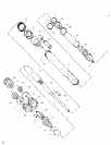
MOTOR DISASSEMBLY
-Remove gearing from tool as previously outlined.
-Remove spacers (69 and 68) and motor assembly from housing.
-Remove cap (52) and shield (53).
-Grasp cylinder in one hand and tap splined end of rotor (58) with
a soft faced hammer; motor will come apart
MOTOR ASSEMBLY
-Pack open bearings with ARO 33153 grease.
-Assemble bearing (56) to end plate (55).
-Assemble end plate (55) to rotor.
-Coat i.d. of cylinder (62 or 63) with spindle oil 29665 and assem-
ble cylinder to end plate (55), aligning air inlet slot of cylinder
and end plate.
-Coat rotor blades (59) with spindle oil 29665 and insert in rotor
slots (straight side out).
-Assemble bearing to front end plate and assemble end plate to
rotor and cylinder.
-Be sure rotor does not bind (if rotor binds tap splined end of rotor
lightly to loosen).
-Assemble shield (53) and cap (52) to end plate (55).
-Assemble motor and spacers (68 and 69) to motor housing
-Assemble gearing and twin drill attachment to tool.
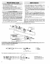
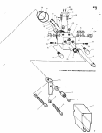
AIR PISTON DISASSEMBLY
-Remove twin drill attachment, gearing and motor assembly as out-
lined elsewhere in this manual.
-Remove cover (1), adapter (3), washer (4) and trip bracket (5)
-Place valve housing in a suitable holding device with the outer
sleeve (41) in an upright position.
-Using a strop type wrench on outer sleeve (41), unthread (L.H
threads) and CAUTIOUSLY remove outer sleeve straight up and
off from valve houslng to prevent bending of air cylinder (35) and
damaging the inside diameter
-Handle the air cylinder (35) with care so its fine cylindrical shape
is not distorted in any manner.
-If the air cylinder remains inside the outer sleeve when sleeve IS
removed, push the piston rod (48) forward then pull it backward
The cylinder will then extend from the sleeve and can now be
removed.
-Remove “0” ring (31), bearing race (32) and retaining ring (49)
-Push piston rod and motor housing out thru gear end of outer
sleeve. Piston (33)
will
drop out when motor housing and piston
rod are removed from outer sleeve.
- Insert
a suitable rod thru gear end of outer sleeve and push muf-
fler cop (38) out thru valve end of outer sleeve
-Piston rod (48) and motor housing (51) are secured with a hard
drying thread adhesive. If it should become necessary to separate
these two parts, heat the threaded area lightly to soften the adhe-
sive and unthread the rod from the housing - R.H. threads.
AIR PISTON ASSEMBLY
NOTICE: When a part containing “0” rings has been removed from
tool, it is recommended that the “0” rings be replaced with new ones
when reassembling part to the tool. Lubricate all “0” rings with ARO
36460 “0” ring lubricant.
-Assemble retaining ring (36), “0” ring (37), “0” ring (39) and
screen (40) to muffler cap (38).
-Assemble muffler cap (38) -screened end first-to outer sleeve
(41) from end of sleeve with internal threads. Push muffler cop
into sleeve until it bottoms against step in sleeve.
-Coat torque pin (42) with grease to retain pin in place and as-
semble inside outer sleeve in hole provided
-Assemble “0” ring (50) to piston rod
-Assemble motor housing and piston rod to outer sleeve thru end
of sleeve with external threads and push piston rod thru muffler
cop using core not to damage “0” ring (37) contained in muffler
cap. Align slot in motor housing with torque pin (42).
-Assemble seals (34) to piston (33) with lips of seals facing away
from each other.
-Assemble piston (33) to piston rod (48) and push piston on rod
until it seats against “0” ring (50) and step on rod.
-Assemble retaining ring (49) to groove in piston rod, securing
piston on rod.
-Assemble bearing race (32) and “0” ring (31) to piston rod and
slide them on rod until they seat against retaining ring (49)
-Clamp valve housing (10) in a suitable holding device with the
threaded end of housing upright.
-Coat i.d. of air cylinder (35) with “0” ring lubricant 36460 and
place air cylinder on valve housing (10) over “0” ring (28).
-Using care not to damage “0” rings (11) contained in housing,
insert piston rod (48) thru housing and carefully locate outer sleeve
over air cylinder and threaded sleeve to housing. Tighten securely
using a strap wrench.
-Assemble motor, gearing, drill attachment, trip bracket and com-
ponents and assemble cover (1) to housing.
VALVE HOUSING DISASSEMBLY
The valve body (14), feed control valves (23) and button bleed valves
(25) can be serviced without removing outer sleeve from valve hous-
ing. To gain access to check valves (17) and components or “0” rings
(11), follow disassembly procedure for removing the air piston.
-Remove both caps (12) and “0” rings (13).
-Push valve body (14) out thru housing. Handle valve body with
reasonable care so the o.d. of valve is not damaged.
-Button bleed valves (25) need not be removed except for
replacement.
VALVE HOUSING ASSEMBLY
-Replace all “0” rings with new ones
-Lubricate “0” rings (15) with 36460 lubricant and assemble to
valve body.
- Assemble “0” rings (22) to needle valves (23) and assemble nee-
dle valves to housing.
Assemble plate (126) to housing, securing with screws (127)
IAssemble valve body to housing and assemble caps (12) with “0”
rings (13) to housing.
-If check valves (17) have been removed, assemble “0” rings (16)
to valves and assemble valves to housing.
-Assemble springs (18) to housing.
-Assemble “0” ring (20) to screw plug (21) and assemble to
housing
-Assemble screw plug (19) to housing
-Assemble outer sleeve and components to housing as described
in air piston assembly section.