


DISASSEMBLY/ASSEMBLY INSTRUCTIONS
l Never apply excessive pressure by a holding device which may
cause distortion of a part
l Apply pressure evenly to parts which have a press fit.
l Apply even pressure to the bearing race that will be press fitted
to the mating port
l Use correct tools and fixtures when servicing this tool.
l Don’t damage “0” rings when servicing tool.
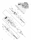
l Use Only genuine ARO replacement parts for this tool. When or-
dering, specify par-t number, description, tool model number and
serial number.
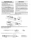
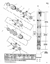
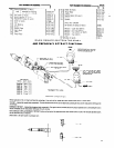
TWIN DRILL DISASSEMBLY
-Using 3mm hex wrench supplied with unit, loosen both adjust-
ment screws (111) completely. IMPORTANT: Alternately unthread
adjustment screws approximately 1/2 turn at a time or unthread
screws simultaneously to prevent damaging the unit.
-Remove body and spindle assemblies from adapter (89).
-Remove retaining ring (93) and pull spindle (90) and components
from adapter (89).
- Using retaining ring pliers, remove retaining ring (96) from gear
(97).
-Remove needle roller (98) and gear (97).
-Remove retaining ring (94) and lock ring (92) from spindle,
-Bearings (95 and 91) ore press fit on driving spindle (90).
-Remove “C” clip (99) from adjustment screws,
-Rotate spindle turret while pulling outward until o portion of spin-
dle aligns with notch in body and remove spindle assembly (108)
from body.
-Remove oil reservoir (106).
-Remove nylon washer (105) by bending slightly.
-Remove nylon washer (101) and gear (102).
-Bearings (103) and spacer (104) are loose parts and will drop out,
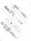
-DO NOT disassemble spindle (108) unless it IS necessary to replace
a port.
-To disassemble, using a flat bottom type punch or similar tool and
an arbor press, remove gear (113) from spindle (125). CARE
SHOULD BE TAKEN TO REPLACE GEAR (113) IN THE SAME POSI-
TION WHEN REASSEMBLING. The gear is assembled with teeth up
on turret stamped “T”. The gear is assembled with teeth down
on turret stomped “B”.
-Remove spindle (125) from sleeve (122) carefully, as six rollers
(120) are loose parts and will drop out. NOTE: Thrust race (121)
IS press fit on spindle.
-Using a “C” type washer that properly fits spindle, press thrust
race off spindle.
-Remove oil seal (124).
- If link bearing (114) and sleeve (122) are removed from turret, it
will be necessary to remove the foam strip (117) first. Lift one end
of foam strip and pull so it slides thru notch under link bearing.
- Using a proper size punch and an arbor press, remove link bearing.
-Press sleeve thru remaining distance in turret,
TWIN DRILL ASSEMBLY
-Pack bearings and coat gears with a good grade of bearing grease
when assembling. Saturate oil reservoirs with a good multigrade
10W/30 oil
-When fitting sleeve (122), it is Important that the slot in the sleeve
lines up with the groove in the back face of the turret. Push foam
strip (117) into the groove in the turret (widest side across groove),
The center of the strip should be under the sleeve and the two
ends should meet at the point opposite the sleeve.
-Press the link bearing (114) over the small end of the sleeve, keep-
ing the 5mm hole in the link bearing aligned with the 5mm hole
in the turret. TO maintain alignment, use a 5mm pin inserted thru
the bore in the link bearing and the turret.
-Assemble oil seal (124) to spindle.
-Assemble thrust race (121) to spindle, pressing an up to the shoul-
der. Be certain thrust race is pressed on and squarely seated, or
premature failure of the bearing may occur.
-Drop the thrust race into the bore of the sleeve assembled in the
turret.
8
-Place a small amount of grease on spindle and position the twenty
needle rollers (123) between the oil seal (124) and thrust race (121)
-Place a small amount of grease on shoulder between the two thrust
races and position the six rollers (120) on spindle.
-Slide spindle into sleeve, insuring foam strip is kept out of the way
-Place a few drops of oil into sleeve and push spindle firmly down
into sleeve.
-Hold spindle in position and turn turret assembly over with gear
end up.
-Apply a small amount of grease to needle cage (116) and slide
cage over the end of the spindle, into the bore of the link bearing
-Place washer (115) over spindle.
-Be certain gear is positioned correctly on spindle. Position with
teeth up on turret stomped “T”. Position with teeth down on turret
stamped “B”. IMPORTANT: When pressing gear on spindle, allow
on end play of .001”.
-Press roll pins (107) into 1/8” diameter holes in turret. Assemble
Set screws (109) to spindle.
-Insert a dummy adjustment screw (111), or a shaft of the same
diameter, thru body from the back or adapter side of body to main-
tain alignment of parts to be assembled into body.
-Assemble one nylon washer (101) over dummy screw and down
into body.
--Assemble bearing (103), spacer (104) and other bearing (103)
to gear (102).
--Assemble gear with bearings to dummy screw, with largest por-
tion of gear going on screw first.
-Assemble one nylon washer (101) to screw.
-Assemble nylon washer (105) to screw, bending slightly to go thru
hole in body.
-Assemble oil reservoir (106) into body and position holes for roll
pins so they will align with roll pins of spindle when spindle is as-
sembled to body.
-Assemble spindle (108) to body and screw, aligning roll pins with
holes in oil reservoir and extended portion of spindle with notch
in body.
-Assemble spring washer (110) and one nylon washer (101) to ad-
justment screw (111).
-Assemble screw (111) to unit, while at the same time withdrawing
dummy screw from unit.
-Assemble “C” clip to screw (111) to secure screw to unit.
-Assemble bearings (91 and 95) to driving spindle (90)
-Assemble gear (97) to driving spindle (go), aligning hole thru gear
with hole in spindle.
-Assemble needle roller (98) thru gear and spindle.
-Assemble retaining ring (96) over gear and needle roller.
-Assemble lack ring to spindle over bearing (95) and assemble
retaining ring (94) to lock ring.
-Assemble driving spindle and components to adapter (89) and
secure with retaining ring (93).
-Assemble the twin drill body assembly to the adapter and lock
ring, alternately threading adjustment screws into lock ring, simi-
lar to disassembly.
-Refer to “spindle adjustment”, page 3
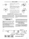
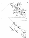
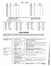
GEARING DISASSEMBLY
-Using wrenches on flats of adopter (89) and ring gear (83), un-
thread adapter from gearing.
-Using wrenches on flats of driving dog (88) and spindle nut (85),
unthread and remove driving dog from spindle. Remove spindle
nut (85) also.
-Thread adjustment screws (6 and 7) all the way back and push
the piston rod (48) all the way forward to expose wrench flats
of motor housing (51) from the outer sleeve (41).
-Using wrenches on fiats of ring gear and motor housing, unthread
gearing from motor housing
-If tool has double gearing, unthread ring gear (83) from ring gear
(81).
-Grasp ring gear in one hand and tap the threaded end of the spin-
dle with a soft faced hammer; spindle and components will loos-
en from ring gear.
-Remove bearing(s) and shafts from spindle to remove planet gears.