


MOTOR SECTION
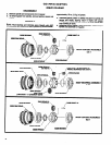
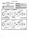
DISASSEMBLY
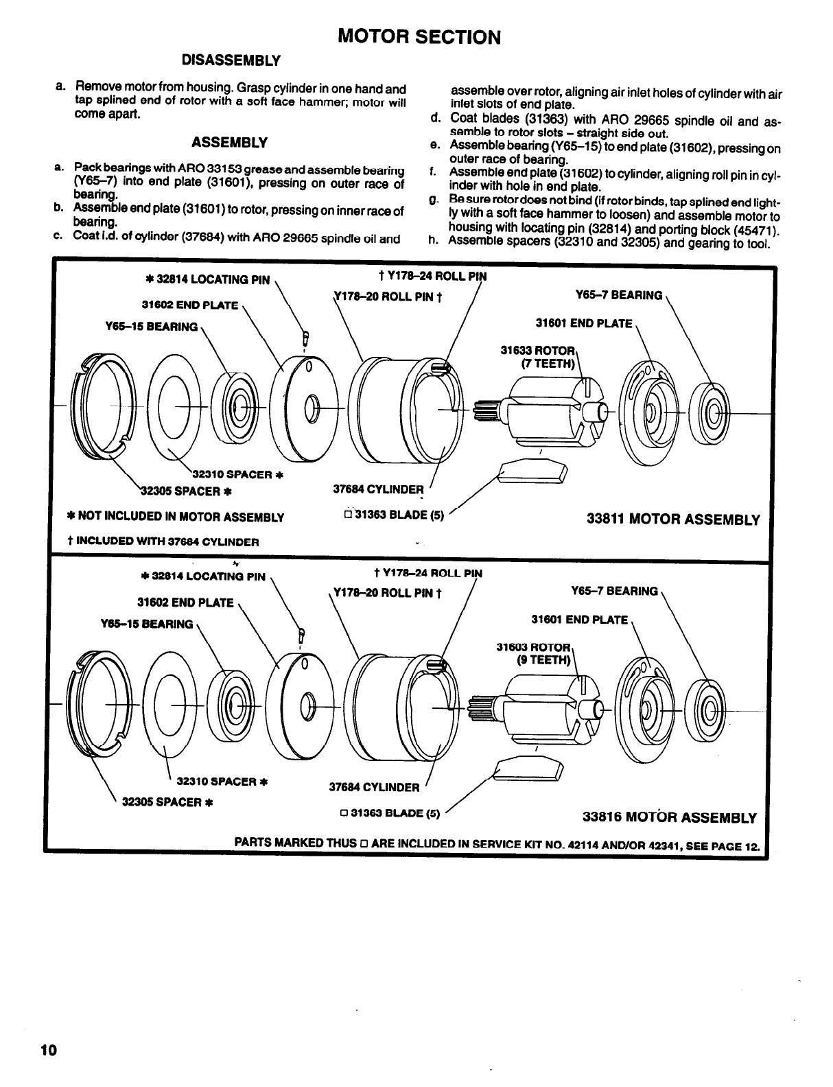
a.
Remove motor from housing. Grasp cylinder in one hand and
tap splined end of rotor with a soft face hammer; motor will
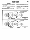
assemble over rotor, aligning air inlet holes of cylinder with air
come apart.
inlet slots of end plate.
d. Coat blades (31363) with ARO 29665 spindle oil and as-
ASSEMBLY
semble to rotor slots - straight side out.
e.
Assemble bearing (Y65-15) to end plate (31602) pressing on
a.
Pack bearings with ARO 33153 grease and assemble bearing
(Y65-7) into end plate (31601), pressing on outer race of
f.
outer race of bearing.
Assemble end plate (31602) to cylinder, aligning roll pin in cyl-
bearing.
inder with hole in end plate.
b.
Assemble end plate (31601) to rotor, pressing on inner race of
g.
Be sure rotordoes not bind (if rotor binds, tap splined end light-
bearing.
ly with a soft face hammer to loosen) and assemble motor to
c.
Coat i.d. of cylinder (37684) with ARO 29665 spindle oil and
h.
housing with locating pin (32814) and porting block (45471).
Assemble spacers (32310 and 32305) and gearing to tool.
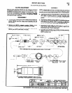
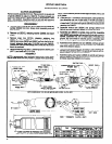
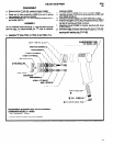
* 32614 LOCATING PIN
31662 END PLATE
Y65-15 BEARING
Y178-24 ROLL PIN
Y65-7 BEARING
31661 END PLATE
31633 ROTOR
32310 SPACER *
2366 SPACER *
* NOT INCLUDED IN MOTOR ASSEMBLY
t INCLUDED WlTH 37664 CYLINDER
37664 CYLINDER
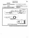
33811
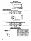
MOTOR ASSEMBLY
31662 END PLATE
Y65-15 BEARING
Y176-26 ROLL PIN t
Y65-7 BEARING
31601 END PLATE
32310 SPACER $
37664 CYLINDER
32365 SPACER
0 31363 BLADE
(5)
33816 MOTOR ASSEMBLY
PARTS MARKED THUS 0 ARE INCLUDED IN SERVICE KIT NO. 42114 AND/OR 42341, SEE PAGE 12.
10