


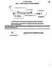

DRIVE SECTION
M30
ADJUSTABLE CLUTCH
33
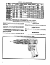
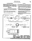
CLUTCH ADJUSTMENT
Remove clutch assembly (36310) from tool. Place pin in hole of
jaw (36318) or wrench on square end of spindle (36311) to adjust
nut (36313). To adjust properly, release nut to least tension. Tight-
en nut one or two positions -each click = one position. Assemble
clutch to tool and test torque on fastener to be tightened. Repeat
until desired torque is obtained.
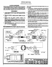
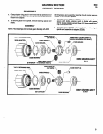
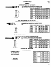
DISASSEMBLY
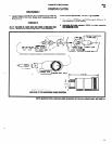
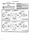
ASSEMBLY
NOTE: Lubricate balls, jaw faces, bit holder shaft, pins and thrust
pad with ARO 40036-1 grease when assembling clutch. Clutch
assembly should contain approximately 1/8 oz. (3.5 g) of grease.
a. Assemble jaw (40772) to spindle (36311) aligning face of jaw
with center of bearing groove in spindle. Assemble balls
(Y16-203) into groove and slide jaw ahead to retain balls in
groove.
a. Remove clutch housing (left hand threads) and bit holder as-
b.
sembly (36322) from tool. Grasp clutch assembly and pull
Assemble key (36319) and jaw (36318) to spindle and secure
from gearing.
with retaining ring (37243). NOTE: Assemble jaw (36318) to
spindle with small hole in face of jaw facing jaw (40772).
b. Remove nut (36313) releasing washer (33609) clutch
spring, pad (36316) pins (36317) and balls (Y16-205).
c. Assemble balls (Y16-205), pins (36317) thrust pad (36316)
clutch spring, washer (33609) and nut (36313). Adjust to de-
c. Remove retaining ring (37243) releasing jaw (36318) key
sired tension (see “Clutch Adjustment”).
(36319) jaw (40772) and balls (Y 16-203).
d. Assemble spring (31092) plug (31093) bit holder assembly
(36322) and bit to spindle and assemble to tool. Assemble
clutch housing to tool.
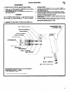
BALL (16) Y 16-203
“O” RING Y 325-8
SPRING
31092,
7
@PIN (6) 36317
NUT 36313
q
BALL Yl6-205
\
(6) 7
WASHER
336091
THRUST PLUG 310933
RETAINING RING 37243
BIT 30320-2
JAW 8 BIT HOLDER
ASS’Y 36322
/
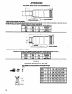
GUIDE ADAPTER IS PRESSED
INTO HOUSING
SEE PAGE 14 FOR ADDlTlONAL GUIDE ADAPTERS
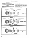
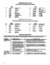
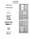
CLUTCH
TYPE
CLUTCH
ASS’Y. NO.
SPRING IDENTIFICATION
SPRING NO. TYPE WIRE WIRE THICKNESS
38310-l
HIGH TORQUE
37872
FLAT
.093” x .188”
38310
MED. TORQUE
36315
FLAT
.062” x .156”
3831 o-2
LOW TORQUE
38512 ROUND
.080” DIAMETER
PARTS
MARKED
THUS
q
ARE
INCLUDED
IN SERVICE KIT NO. 42114 AND/OR
42341, SEE PAGE 12.
5