


HEAD SECTION
M30
33
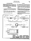
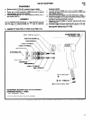
DISASSEMBLY
a. Remove roll pin (Y178-25), releasing trigger (45469).
b. Remove screw (Y222-156-C) releasing shroud (45468).
c. Grasp end of valve assembly (47880) and pull to remove
valve assembly and bushing (45465).
d. Remove retaining ring (Y147-68), releasing screens (42911)
and muffler (45474).
ASSEMBLY
NOTE: Whenever a part containing “O” rings has been removed
from the tool, it is recommended the “O” rings be replaced.
Grease all “O” rings before assembly.
a. Assemble “O” rings (Y325-13, Y325-12 and Y325-11) to
bushings (45465).
b.
Assemble “O” ring (Y325-7) to valve assembly (47680).
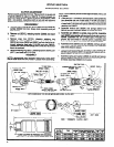
c.
Lubricate plunger (47879) and valve assembly (47860) with
ARO 29665 spindle oil.
d.
Assemble springs (48806-l) to valve assembly (47880).
e.
Assemble plungers (47879) and valve assemblies (47880) to
bushings (45465) and assemble bushings to housing, align-
ing flats of bushings with flats of shroud.
f.
Assemble shroud (45468) to housing, securing with screw
(Y222-156-C).
g.
Assemble trigger to shroud, securing with roll pin (Y178-25).
h. Assemble muffler (45474) and screens (42911) to housing,
securing with retaining ring (Y147-68).
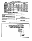
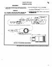
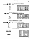
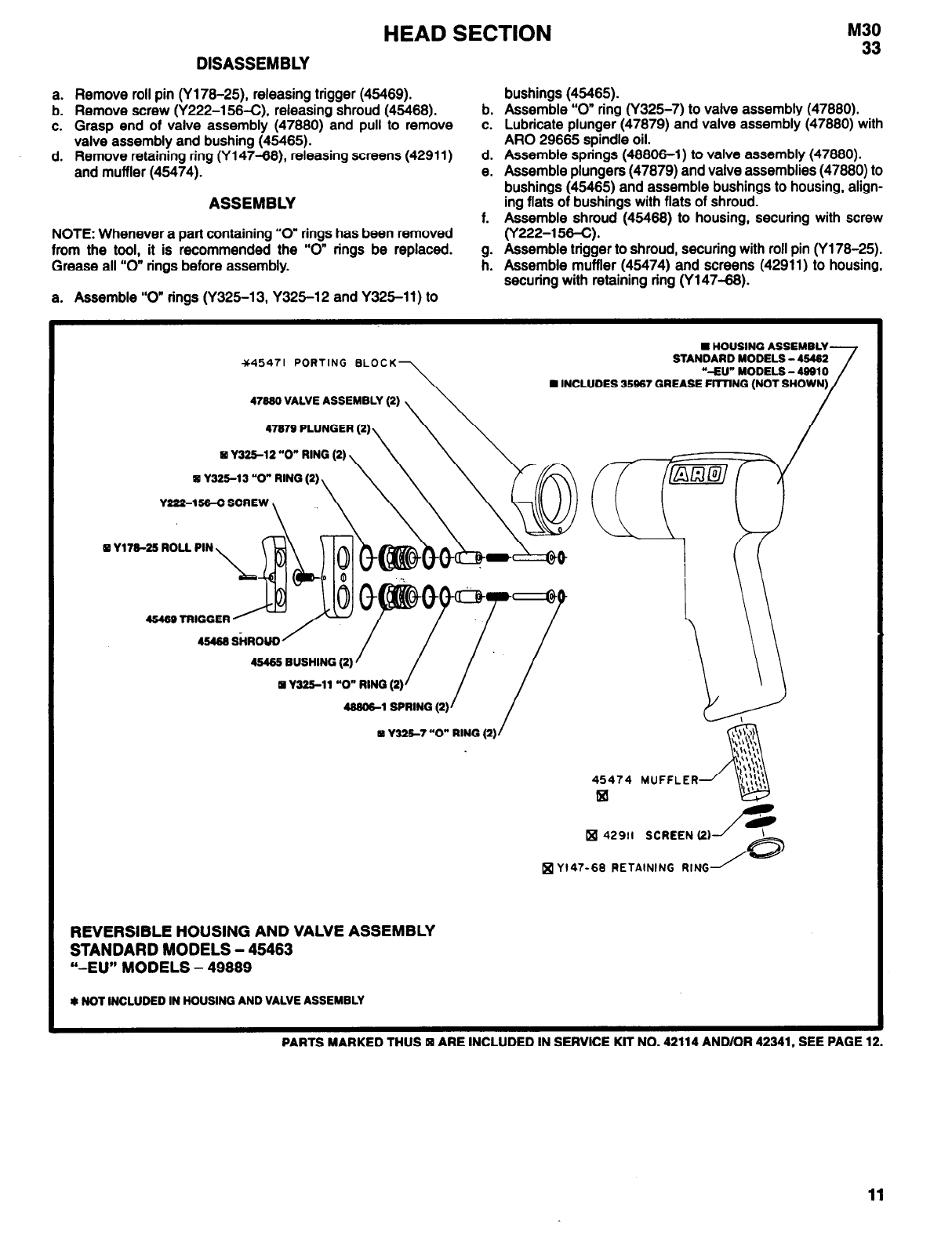
45471 PORTING BLOCK
47990 VALVE ASSEMBLY (2)
47979 PLUNGER (2)
Y325-12 “O” RING (2)
q Y225-13 “O” RING (2)
Y222-156-C SCREW
n HOUSING ASSEMBLY
STANDARD MODELS - 49492
“-EU” MODELS - 49910
Y179-25 ROLL PIN
45469 TRIGGER
45465 BUSHING (2)
Y225-11 “O” RING (2)
49906-1 SPRING (2)
Y325-7 “O” RING (2)
45474 MUFFLER
q
42911 SCREEN (2)
Y147-68 RETAINING RING
REVERSIBLE HOUSING AND VALVE ASSEMBLY
STANDARD MODELS - 45463
“-EU” MODELS - 49889
* NOT INCLUDED IN HOUSING AND VALVE ASSEMBLY
PARTS MARKED THUS ARE INCLUDED IN SERVICE KIT NO. 42114 AND/OR 42341, SEE PAGE 12.
11