


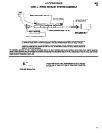
DRIVE SECTION
TORQMATIC CLUTCH
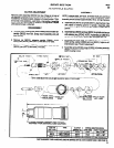
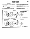
CLUTCH ADJUSTMENT
Remove clutch assembly from tool. Place wrench on square end
clutch. Clutch assembly should contain approximately 1/8 oz. (3.5
of spindle (38322) to adjust nut (38313). To adjust properly, re-
g) of grease.
lease nut to least tension. Tighten nut one or two positions -each
a.
click = one position. Assemble clutch to tool and test torque on
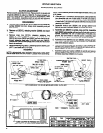
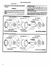
Place jaw (40771) on bench, cam face down, start spindle into
fastener to be tightened. Repeat until desired torque is obtained.
jaw, assemble one row of steel balls (Y16-204) and slide to
shoulder of spindle. Invert spindle and jaw, assemble balance
DISASSEMBLY
of steel balls (Y16-204) and spacer (38318) and secure with
a. Remove clutch housing (left hand threads) and bit holder as-
retaining ring (38327).
sembly (38322) from tool. Grasp clutch assembly and pull
b. Assemble lockout cam (38324) and springs (38313 and
from gearing.
36314) into end of spindle (38322) in proper sequence.
b. Remove nut (36313) releasing washer (33809) and clutch
c. Assemble cam (38321) to spindle, tang end first. Assemble
spring.
cam (36320) onto spindle until cam face is flush with groove in
c. Remove snap ring (31124) releasing retaining ring
spindle, assemble first row of steel balls (Y16-203) into
(37241-l), retainer (38317) and spring (44888). Driver
groove, slip cam ahead to second groove, assemble steel
(36319) and cams (38320 and 38321) are now free to be re-
balls into second groove and slide cam ahead to secure.
moved, releasing steel balls (Y16-203) and pins (38325).
d. Assemble driver (38319) over cam (38320) until face is flush
Lockout cam (38324) and springs (38313 and 38314) are now
with holes in spindle, assemble pins (38325) into holes and
free to be removed.
slide drive ahead to secure.
d. Remove retaining ring (38327) releasing spacer (38316) jaw
e. Assemble spring (44868) over shoulder of cam (38320) as-
(40771) and steel balls (Y16-204).
semble spring retainer (38317) to spindle and secure with re-
,
ASSEMBLY
tainers (37241-l) and snap ring (31124).
f.
NOTE: Lubricate balls, pins, jaw faces, lockout cam, cams, driver
and bit holder shaft with ARO 40036-l grease when assembling
Assemble spring and washer (33609) to spindle and secure
with nut (36313). Adjust to desired tension and assemble with
bit holder assembly (36322) into housing.
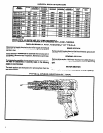
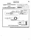
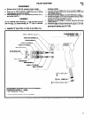
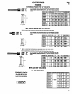
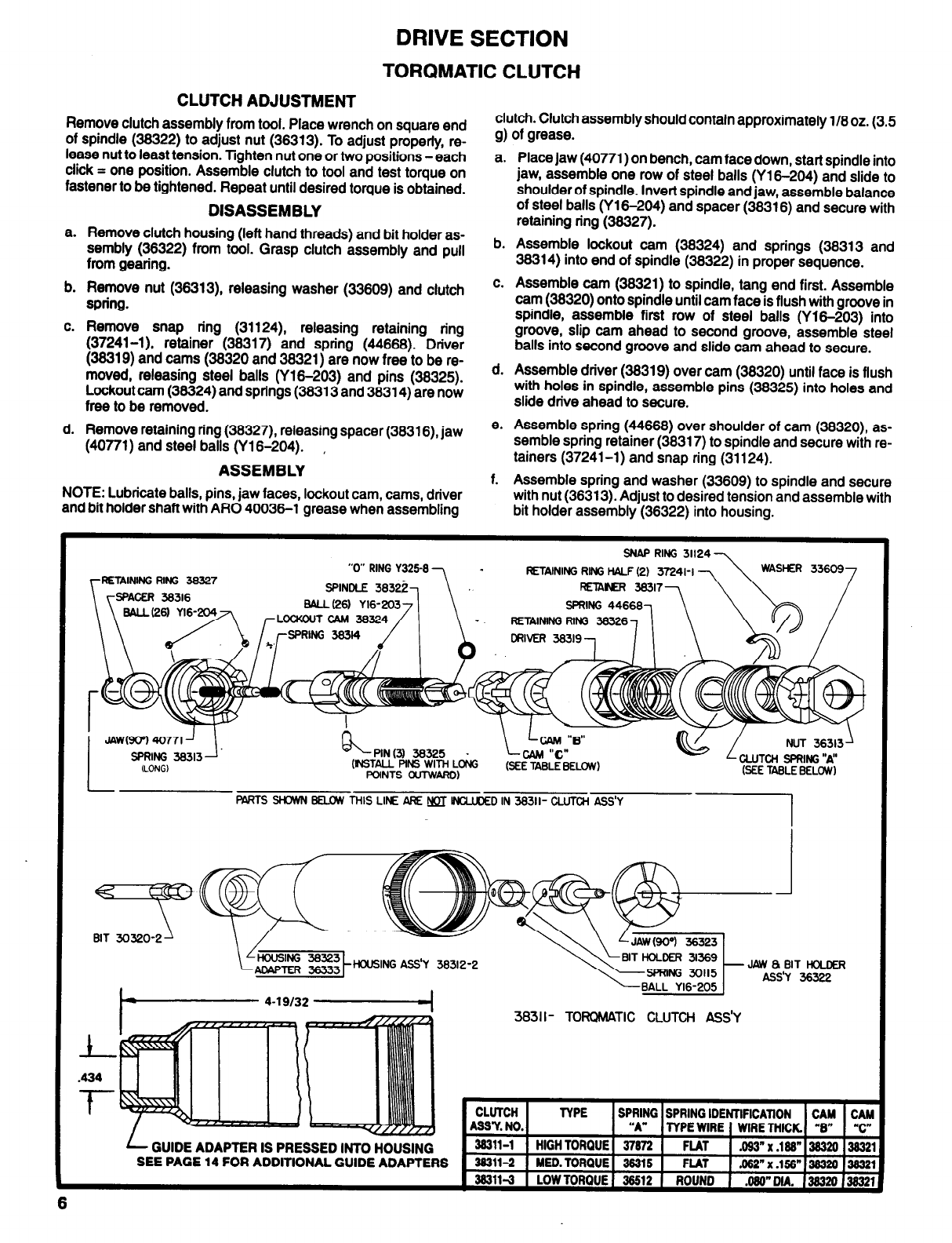
SNAP RING
31124
RETAINING RING 36327
RETAINING RING HALF (2)
RETAINER 38317
RETAINING RING 36326
PIN (3) 36325
.
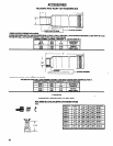
PARTS SHOWN BELOW THIS LINE ARE NOT lNCLUDED IN 38311- CLUTCH ASS’Y
BIT 30320-2
HOUSING ASS'Y 38312-2
GUIDE ADAPTER IS PRESSED INTO HOUSING
SEE PAGE 14 FOR ADDITIONAL GUIDE ADAPTERS
3831 I- TORQMATIC CLUTCH ASS’Y
6