


10 04662995_ed4
Maintenance
WARNING
Always wear eye protection when operating or
performing any maintenance on this starter. Always turn
off the air supply and disconnect the air supply hose
before installing, removing or adjusting any accessory
on this starter or before performing any maintenance on
this starter.
Lubrication
Each time a Series ST600 Starter is disassembled for
maintenance or repair, lubricate the starter as follows:
1. Lubricate the inside diameter of the Drive Shaft (17) with
Ingersoll Rand No.130 Grease.
2. Lubricate the Pinion end of the Drive Shaft with
Ingersoll Rand No.11 Grease.
3. Wipe a thin film of Ingersoll Rand No.130 Grease in the
bore of the Drive Housing (12).
4. Roll the Piston Return Spring (18) in Ingersoll Rand
No.130 Grease.
5. Coat the outside of the Piston (15) with Ingersoll Rand
No.130 Grease.
6. Lubricate all O-Rings with O-Ring lubricant.
Disassembly
General Information
1. Do not disassemble the Starter any further than
necessary to replace worn or damaged parts.
2. When grasping a part in a vise, always use leather-
covered or copper-covered vise jaws to protect the
surface of the part and help prevent distortion. This is
particularly true of threaded members.
3. Do not remove any part which is a press fit in or on a
subassembly unless the removal of that part is necessary
for replacement or repairs.
4. Always have a complete set of seals and O-Rings on
hand before starting any overhaul of a Series ST600
Turbine Starter. Never reuse old seals or O-Rings.
5. Do not press any needle bearing from a part unless you
have a new needle bearing on hand for installation.
Needle bearings are always damaged during the removal
process.
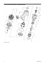
Disassembly of the Starter
1. Place the Starter on a workbench with Exhaust end
down.
2. Remove the Drive Pinion Retaining Screw (24).
NOTICE
Models ending in R31, R51, R83, R91 and R942 have a
left-hand thread. Models ending in L31, L51, L83, L91 and
L942 have a right-hand thread.
3. Remove the Drive Pinion (23) with Pinion Collar attached
off the Drive Shaft.
4. Unscrew and remove the eight Drive Housing Cap
Screws (20).
5. Remove Drive Housing (21).
6. Remove Spring (18) and seat (19).
7. Slide the Drive Package Assembly (17) from the Drive
Housing.
8. Place Motor Housing (12) in a copper faced vise
clamping on the flats of the Exhaust Cap (4).
9. Insert a rod in the inlet and turn counterclockwise to
remove exhaust cover (4).
NOTICE
Transmission Fluid will drain and build-up on the
Exhaust Cover. Handle Exhaust Cover with care.
10. Remove Motor Housing from vise and place on
workbench with Exhaust end upward.
11. Grasp the rear of the Motor Assembly (6) and pull it from
the rear of the Motor Housing.
12. Place Motor Housing in drip pan with Exhaust end down
to allow transmission fluid to drain.
13. Press on clutch Shaft through the front end to release
Gear Package (10) and Front Deflector (7).
Assembly
General Instructions
1. Always press on the inner ring of a ball-type bearing
when installing the bearing on a shaft.
2. Always press on the outer ring of a ball-type bearing
when pressing the bearing into a bearing recess.
3. Whenever grasping a starter or part in a vise, always use
leather-covered or copper-covered vise jaws. Take extra
care with threaded parts or housings.
4. Except for bearings, always clean every part and wipe
every part with a thin film of oil or stated type of grease
before installation.
5. Check every bearing for roughness. If an open bearing
must be cleaned, wash it thoroughly in a suitable
cleaning solution and dry with a clean cloth. Sealed or
shielded bearings should never be cleaned. Work grease
thoroughly into every open bearing before installation.
6. Apply a film of O-ring lubricant to all O-rings before final
Assembly.
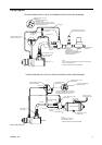
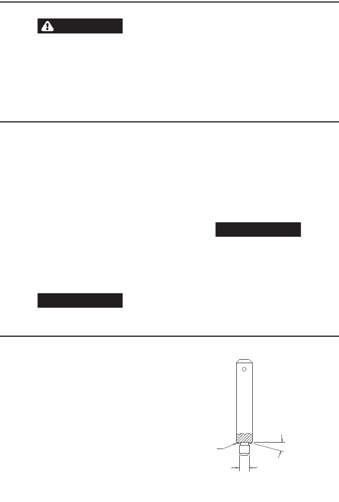
7. Unless otherwise noted, always press on the stamped
end of a needle bearing when installing the needle
bearing in a recess. Use a bearing inserting tool similar to
the one shown in Dwg.TPD786.
(Dwg.TPD786)
NEEDLE BEARING INSERTING TOOL
SHOULDER TO
REGULATE DEPTH
PILOT TO FIT I.D. OF BEARING.
LENGTH OF PILOT TO BE
APPROXIMATELY 1/8” LESS THAN
LENGTH OF BEARING
15°