


04662995_ed4 11
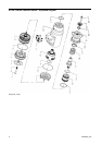
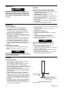
Assembly of the Starter
1. Place Motor Housing on a workbench, exhaust end up.
2. Grasp Gear Package Assembly (10) and insert into Motor
Housing. Rotate Gear Package to align Planet Gear
Teeth with Ring Gear Teeth.
3. Place Wave Spring (9) onto Front Deflector (7).
4. Insert Front Deflector (7) into Motor Housing applying
force until it seats against Ring Gear.
5. Add 275 ml of Dextron®** II Automatic Transmission fluid
through the hole in the Front Deflector.
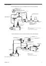
6. Before installing the Motor Assembly, coat the O-Rings
on the Motor Assembly and the inside of the Cylinder with
O-Ring lubricant. Install the Motor Assembly through the
rear of the Motor Housing with geared end of the rotor
toward the front.
NOTICE
Be careful not to damage O-Rings during assembly. If
necessary a .010” thick sleeve may be inserted to cover
inlet hole. Remove once Motor Assembly has been
installed.
7. Coat the Exhaust O-Ring (5) with O-Ring lubricant and
install in the groove on the Exhaust Cap (4).
8. Align the Exhaust Cap in the rear of the Motor Housing
and rotate until it seats. Tighten the Exhaust Cap to a
final torque of 50 ft.-lb.
NOTICE
After assembling the exhaust cover to the starter, add
20 ml of Dextron® **II Automatic Transmission Fluid
through the screw hole in the Exhaust Cover.
** Registered Trademark of Exxon Corp.
9. Install the Deflector (3), Spring (2) and Screw (1) in the
rear of the Housing Exhaust Cover.
NOTICE
Coat the threads of the Deflector Retaining Screw with
Ingersoll Rand SMB-441 Sealant.
10. Place Starter in vise with exhaust end down clamping on
flats of Exhaust Cap.
11. Grasp Drive Package Assembly and align the spline teeth
of Drive Package Assembly with spline teeth of the Gear
Package Assembly. Apply pressure until Piston is seated.
12. Install Spring (18) and Seat (19).
13. Carefully position the Drive Housing (12) onto the Motor
Housing.
14. Install the Drive Housing Cap Screws (20) and torque to
20-25 ft-lbs.
15. Refer to TPE_1027 for proper orientation.
16. Install Pinion (23) with Collar (22) attached. Align the
notches of the Pinion with notches in the Drive Shaft.
17. Install the Drive Pinion Retaining Screw (24) into the end
of the Drive Shaft and torque to 180-220 ft-lb.
NOTICE
Models ending in R31, R51, R83, R91 and R942 have a
left-hand thread. Models ending in L31, L51, L83, L91 and
L942 have a right-hand thread.
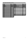
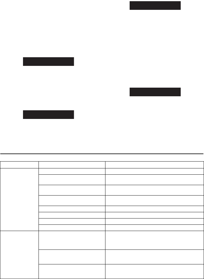
Troubleshooting Guide
Trouble Probable Cause Solution
Motor will not run No air supply Check for blockage or damage to air supply lines or tank.
Damaged motor assembly Inspect Motor Assembly and power train and repair or
replace if necessary.
Foreign material in motor and/or piping Remove Motor Assembly and/or piping and remove
blockage.
Blocked exhaust system Remove Housing Exhaust Cover (1) and check for
blockage.
Defective Control Valve or Relay Valve Replace Control Valve or Relay Valve.
Low air pressure to Starter Check air supply.
Restricted air supply line. Check for blockage or damage to air lines.
Relay Valve malfunctioning Clean or replace lines or Relay Valve. Lube relay Valve.
Loss of Power Exhaust flow restricted Check for blocked or damaged piping. Clean or replace
piping. Check for dirt or foreign material and clean or
remove. Check for ice build-up. Melt ice and reduce
moisture build-up to Starter.
Worn motor parts Remove the motor from the Motor Housing (17) and
disassemble the motor. Examine all parts and replace any
that are worn or damaged.
Lack of air to starter Check for clogged or damaged air line between relay valve
and starter. Check relay valve to determine if it is
functioning properly. Check air tank.