


4 04662995_ed4
Installation
NOTICE
For maximum performance, read this manual prior to
installation or operation of Series ST600 Starters.
General Information
1. This starter is designed for flange mounting at the inlet.
The Flange Mounting Kit is required for installation. All
Piping, hoses and valving must be clean prior to
installation. Make sure that the starter inlet is free of dirt
and foreign material during installation.
2. Engine design often requires mounting the starter
underneath in extremely close quarters, and even though
two of the mounting bolt holes are easy to reach, the third
one is less accessible. To install a starter, the following
tools are required: regular ratchet wrench, sockets,
universal joint, socket extension and single or double-end
box wrench.
3. Improper hook-up impairs the efficiency of a Starter.
Pressure Lines smaller than those recommended will
reduce the volume of air to the motor and the use of
reducers for piped-away applications in the exhaust port
will restrict the exhaust causing back pressure to the
motor resulting in reduced performance. Keep the
number of tees and elbows, and the length of the supply
line upto a minimum. Use 1-1/2” hose or pipe for supply
lines up to 15 feet long: use 2” hose or pipe if the supply
line is over 15 feet long.
4. Install a 300 mesh strainer in the inlet line for each starter.
These 300 mesh strainers provide 50 micron filtration and
offer significant protection against supply line
contaminants which could damage the turbine
components. Ingersoll Rand offers 3 sizes:
ST900-267-24 for 1-1/2 inch lines, ST900-267-32 for 2
inch lines and ST900-267-64 for 4 inch lines.
Replacement elements are: ST900-266-24 for 1-1/2 inch,
ST900-266-32 for 2 inch and ST900-266-64 for 4 inch
lines.
5. Make your connections bubble tight to avoid unnecessary
costs and delays. On all threaded connections
throughout the system, use Ingersoll Rand No.SMB-441
Sealant, non-hardening No.2 Permatex or always run the
air supply line for the side or top of the receiver, never at
or near the bottom. Moisture in the air collects at the
bottom of the receiver resulting in damage which could
cause the valves to become inoperative. Periodically,
open the petcock at the bottom of the tank to drain the
water.
6. We recommend installation of a “glad hand” in vehicular
applications for emergency re-pressurizing of the system.
To keep the “glad hand” clean and free of dirt and to
protect it from damage, a second “glad hand” closed by a
pipe plug can be mated to it, or a “glad hand” protector
bracket can be used.
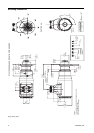
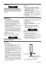
Orientation of the Starter
If the factory orientation will not fit your engine due to radial
location of the Drive Housing or location of the inlet and/or
exhaust ports, re-orient the starter as follows:
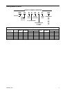
1. Refer to the dimension illustration and note that the drive
housing can be located in anyone of eight radial positions
relative to the air inlet (motor housing).
2. Study the engine mounting requirements, and determine
the required orientation of the Drive Housing relative to
the Gear Case. If the Drive Housing has to be reoriented,
remove the eight Drive Housing Cap Screws and rotate
the Drive Housing to its required position.
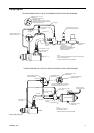
Mounting the Air Starter
1. Study the Piping diagram on Page 5.
2. The air receiver tank for a starter installation must meet
SAE J10B specifications. It must have a working
pressure capability equal to or greater than the maximum
pressure at which the starter will be operated.
3. When connecting the starter to a receiver tank that is
already in service, bleed off the air pressure by opening
the drain valve.
WARNING
Bleed off the air pressure through a valve or petcock. Do
not remove a plug from the tank while the tank is still
pressurized. Drain off any water that has accumulated in
the bottom of the tank.
4. Using a 1-1/2” short nipple, install the SRV150 Starter
Relay Valve on the end of the receiver tank as shown in
the piping diagram.
NOTICE
Make certain the connection is made to the inlet side of
the Relay valve indicated by the word “IN” cast on the
valve body.
5. Install the No.SMB-G618 Starter Control Valve on the
dash panel (for vehicular installations) or some other
appropriate panel (for stationary installations.)
6. Mount the No.150BMP-1064 Air Pressure Gauge on or
adjacent to the control panel. It should be located where it
is readily visible to the operator of the Control Valve.
7. Connect the Starter Control Valve to the Relay Valve with
1/4” hose. Install a Tee in this line with a short feeder
hose to the Pressure Gauge.
NOTICE
Make certain the hose is connected to the “SUPPLY”
side of the Starter Control Valve.
8. To determine the exact length of 1-1/2” air hose required,
run a piece of heavy-duty hose or some other flexible
tubing of the same diameter from the Relay Valve on the
receiver to the starter location on the engine.
9. Attach the 1-1/2” air hose to the outlet side of the Relay
Valve, and run the hose through the frame to its final
position at the starter location.
10. At this point, determine if it is feasible or practical to
attach the hose to the starter before or after the starter is
actually mounted. In many cases, it may be necessary to
attach the hose to the starter before mounting.
11. If possible, liberally grease the teeth on the ring gear with
a good, sticky gear grease or motorcycle chain lube. This
will help promote the life of the ring gear and the Starter
Pinion.
12. Place the starter into position, and mount it on the
flywheel bell housing. Tighten the mounting bolts to
100-ft-lb (136 Nm) of torque.
13. Pressurize the complete starting system and check every
connection with a soap bubble test. There must be no
leaks.