


M35
41
MAINTENANCE SECTION
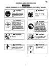
Always wear eye protection when operating or
performing maintenance on this tool.
Always turn off the air supply and disconnect the air
supply hose before installing, removing or adjusting any
accessory on this tool, or before performing any
maintenance on this tool.
LUBRICATION
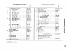
Each time a WG068A-F4 Impact Wrench is disassembled
for maintenance and repair or replacement of parts,
lubricate the tool as follows:
1.
2.
3.
4.
5.
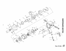
Work approximately 12 to 15 cc of IRAX No. 100
Grease into the impact mechanism, particularly around
the Hammer Pins (37), Hammer (38), Hammer Frame
(36), Anvil (39) and inside the Hammer Case Bushing
(32).
Work some IRAX No. 100 Grease into the Rear Rotor
Bearing (18) and Front Rotor Bearing (27).
Inject approximately 4 cc of IRAX No. 100 Grease
into the Grease Fitting (12).
Wipe a thin film of IRAX No. 50 Oil on the Rotor (2 1),
Vanes (22), Reverse Valve (13), Rear End Plate (19),
Front End Plate (25) and the bore of the Cylinder (23).
Use IRAX No. 50 Oil for lubrication the motor. Inject
approximately 1 to 2 cc of oil into the air inlet before
attaching the air hose.
DISASSEMBLY
The Hammer is now free to slide from the Hammer
Frame. Be careful not to drop it.
General Instructions
Disassembly of the Reverse Valve
1.
2.
3.
4.
2.
Do not disassemble the tool any further than necessary
to replace or repair damaged parts.
Whenever grasping a tool or part in a vise, always use
leather-covered or copper-covered vise jaws to protect
the surface of the part and help prevent distortion. This
is particularly true of threaded members and housings.
Do not remove any part which is a press lit in or on a
subassembly unless the removal of that part is
necessary for repairs or replacement.
Do not disassemble the tool unless you have a
complete set of new gaskets and G-rings for
replacement.
Slide assembled motor out of Motor Housing.
Disassembly of the Impact Wrench
1. Clamp the handle of the tool in leather-covered or
copper-covered vise jaws with the square driver
upward.
2. Unscrew and remove the four Hammer Case Cap
Screws (33).
3. While lightly tapping on the end of the Anvil (39) with
a plastic hammer, lift off the Hammer Case (3 1) and
remove the Hammer Case Gasket (30).
4. Grasp the Hammer Frame (36) and carefully lift off the
entire impact mechanism, making certain not to drop
the two Hammer Pins (37).
Disassembly of the Impact Mechanism
1. Set the mechanism, driver end up, on the workbench.
Using a felt tipped pen, mark one end of the Hammer
“?” with the arrow pointing upward.
2. With the mechanism sitting upright on the workbench,
slowly rotate the Anvil in a clockwise direction until it
comes up solid.
If you continue to rotate the Anvil, it will cam the
Hammer out of engagement. Don’t do this; merely
rotate the Anvil until it comes up solid.
3. Hold the Hammer Frame (38) firmly and, without
disturbing the Hammer, gently lift the Anvil from the
Hammer Frame.
4. With the Anvil removed, lift out the two Hammer Pins
(37).
1. Unscrew the Reverse Valve Knob Screw (16) and
remove the Reverse Valve Knob (15).
This Screw is installed with LoctiteB*. You may
have to heat the Screw slightly to loosen it.
2. While slowly rotating the Reverse Valve (13),
withdraw it from the reverse valve bushing in the
Motor Housing. Remove the Housing from the vise.
Disassembly of the Motor
1. Grasp the Motor Retainer (29) and lift it from the
Motor Housing (1).
2. Lift the Rear Hammer Frame Washer (35) and the two
Motor Clamp Washers (28) from the front of the motor.
3. Grasping the spline of the Rotor (21), carefully lift the
assembled motor from the Motor Housing.
* Registered trademark of Loctite Corporation.