55
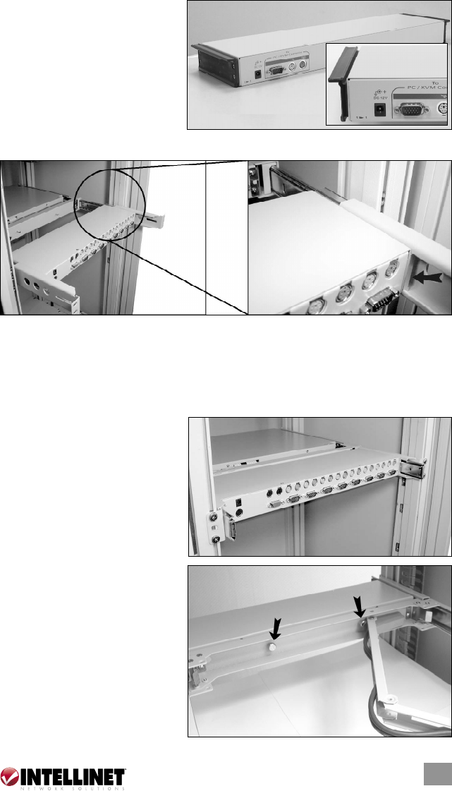
6. Attach the extensions (from the
rear bracket and extension
kit) to both sides of the KVM
switch module. NOTE: For a
2U module (Model 521871),
the extensions are mounted
to the lower half of the
module. In the inset at right,
you can also see that the wider lip is the top of the plastic extension.
7. The rear brackets, extensions and slide rails need to fit tightly. As shown
above-left, slide the rear brackets onto the extensions. Then, as shown above-
right, insert both sliding rails of the console drawer into the tight space
formed by the rear brackets and the extensions. Holding the KVM switch
module on both sides, push it in evenly.
8. Push the rear brackets all the
way in and fasten them
securely.
9. Slide the console drawer
out to gain access to the
connecting screws. Push the
KVM switch module evenly
toward the connector
attached to the console
drawer and lock both units
together by tightening the
screws indicated by the
arrows.


