


11
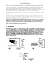
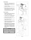
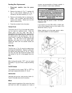
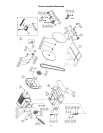
Sanding Disc Replacement
1. Disconnect machine from the power
source.
2. Remove the knobs (A, Fig. 7), washers (B,
Fig. 7), and trunnion holders (C, Fig. 7)
followed by the table assembly (D, Fig. 7).
3. Remove old sanding disc by striping from
wheel. Use a cleaner and putty knife to
remove the residue. Make sure the disc
plate is clean and dry.
4. Press the new disc firmly into place.
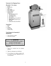
Center Point
The center point (E, Fig. 8) provided with sander
can be used for sanding circles. Slide the
center point into the miter slot that is
perpendicular to the sanding disc. The radius of
the desired circle should be the distance from
the center point to the sanding disc. Lock the
center point in position by tightening the set
screws. Cut the wood to the approximate
diameter and press on to the center point.
Rotate the wood until the desired results are
achieved.
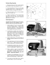
Filler Bar
The filler bar (J, Fig. 8) should be added when
sanding small workpieces. Secure in place with
the socket head cap screw (K, Fig. 8). When
not using the filler bar thread the socket head
cap screw (K, Fig. 8) in the tapped hole as a
stop.
Brake
After turning the sander “OFF” you can press
the brake (F, Fig. 8) to slow, or stop the sanding
disc.
On/Off Switch
The machine can be turned “ON” or “OFF” by
pushing the appropriate button (G, Fig. 8).
Lubrication
Lubricate the trunnion, and trunnion holder (H,
Fig. 8) if the table does not tilt smoothly.
Motor
Make frequent inspections of the motor fan cover,
and blow out (with low pressure air hose) or
vacuum any accumulation of foreign material in
order to maintain normal motor ventilation.
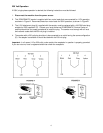
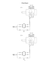
WARNING
All electrical connections must be done by
a qualified electrician. All adjustments or
repairs must be done with the sander
disconnected from the power source,
unplugged. Failure to comply may result in
serious injury!
The PDS-12CS disc sander is rated 115V/230V,
Prewired 115V.
If you want to run the PDS-12CS on 230V refer
to the wiring diagram found on the inside of the
switch box cover (I, Fig. 8).
Before hooking up to the power source, make
sure that the switch is in the off position.