


9
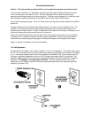
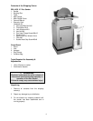
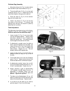
Stand Assembly
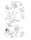
1. With the help of another person lift the
sander (A, Fig. 1) onto the stand (B, Fig. 1).
Feed the belt (C, Fig. 1) through the cut out
in the top of the stand.
2. Match the hole pattern in the stand with the
hole pattern in the sander.
3. Bolt the sander to the stand with four
M10x35 socket head cap screw (D, Fig. 1),
four M10 lock washers (E, Fig. 1) and four
M10 flat washers (F, Fig. 1). Tighten the
nuts to secure the sander to the stand.
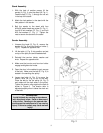
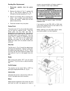
Sander Assembly
1. Unscrew the knob (G, Fig. 2), remove the
washer (H, Fig. 2) and the trunnion holder (I,
Fig. 2). Repeat for opposite side.
2. Lift the table (J, Fig. 2) into position and set
on top of the split pins and threaded shaft.
3. Reinstall the trunnion holder, washer and
knob. Repeat for opposite side.
4. Make sure the trunnion and trunnion holder
engage and tighten the knobs.
5. Open the door in the cabinet to gain access
to the belt. Make sure the belt (K, Fig. 3) is
seated in the sanding disc pulley.
6. Loosen two bolts (L, Fig. 3) to move the
tension roller (M, Fig. 3) out of the way.
Place the belt on the fan pulley (N, Fig. 3)
and rotate until the belt seats in the pulley.
Tighten the tension roller against the belt as
shown in Figure 3. The tension roller is
adjusted properly when it takes the slack out
of the belt.
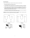
WARNING
Avoid kickback by sanding in accordance
with directional arrow. Sand on downward
side of disc. Sanding on the upward side
could cause the workpiece to fly up causing
injury! Failure to comply may cause serious
injury!