


10
Assembly
Tools required for assembly:
1 Flat head screwdriver
1 Set of open-end wrenches
1 Set of Hex wrenches
1 Adjustable wrench
Installing Drum Head
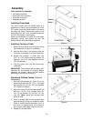
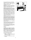
The drum sander must be bolted down to a
workbench or stand. If you purchased one of the
JET stands, place the sander base on the stand
and align the holes. Secure the sander to the
stand using four 3/8” x 3/4” hex cap screws and
four 3/8” flat washers. See Figure 4.
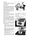
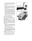
Attach the handwheel (A, Figure 6) to the height
adjustment screw, and tighten the two set
screws with the 4mm hex wrench supplied.
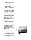
Installing Conveyor Table
1. Raise the drum as far as it will go by turning
the handwheel (A, Figure 5) clockwise.
2. Align the four holes in the conveyor with the
four holes in the base of the drum assembly.
3. Secure the conveyor in place with four
5/16”-18 x 3/4” socket head cap screws (B,
Figure 5), four 5/16” lock washers and four
5/16” flat washers.
4. Plug the motor cord into the control box
receptacle.
IMPORTANT: The conveyor belt has been over-
tensioned for the purpose of shipping. Before
operating the sander, adjust the belt tension
according to instructions on page 15.
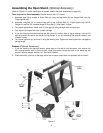
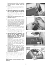
Infeed and Outfeed Tables (Optional
Accessory)
1. Bolt the base bracket (B, Figure 6) to the
sander base with two 3/8”-16 x 1” hex head
cap screws (C) and two 3/8” flat washers
(D). Tighten the screws.
2. Mount the table (A) to the base bracket (B)
with four 1/4"-20 x 3/4" carriage bolts (E),
four 1/4" flat washers (F) and four 1/4" hex
nuts (G). Note: Leave the carriage bolts
loose for now.
3. Place a straight edge on the conveyor bed
and extending out over the extension table.
Raise or lower the extension table until it is
level with, or slightly below, the surface of
the conveyor belt. Tighten the hex nuts (G).
4. Repeat for the other table.
Figure 4
Figure 5
Figure 6