


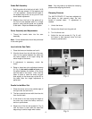
3
XACTA FENCE II™ COMMERCIAL 30/50
Note: This manual also runs through the steps of installing the rails, and extension table.
WARNING
Disconnect the table saw from the power source before attempting any assembly or adjustment!
Failure to comply may cause serious injury!
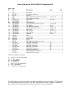
Contents of the Shipping Containers
1 XACTA FENCE II™
1 Front Rail
1 Rear Rail
1 Guide Rail
3 Black Plastic End Caps
1 Hardware Package
1 Owner’s Manual
1 Warranty Registration Card
Tools Required for Assembly & Adjustment
1 #3 Cross Point Screwdriver
1 7/16” Wrench
1 1/2" Wrench
1 Combination Square & Straight Edge
1 Electric Drill
1 1/4”, 3/16” Drill Bits
2 4”-6” C-Clamps
1 1/4”, 3/16” Allen Wrenches
Front and Rear Rail Assembly
Note: The hardware should be packed in the
guide rail along with the end caps.
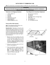
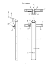
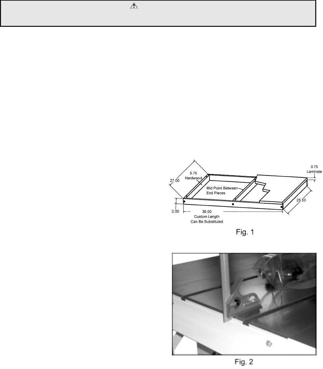
Assembly Note: Depending on the size of the
extension table you are using, you may need to
remove the right side extension wing. You need
to have four bolts attaching the extension table
to the front and rear rails. Use a JET extension
table or one designed and built by the operator.
If you are planning to build a table, see Figure 1
for the dimensions.
1. Bolt the front rail to the table (not to the
extension wing at this time) with two 1/4”-20
x 1-1/4” hex cap screws, four 1/4” flat
washers, two 1/4” lock washers and two 1/4”
hex nuts. Tighten just enough to hold the
rail next to the table but keep loose enough
to allow height adjustment.
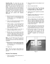
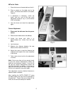
2. Setting the combination square at 9/16” will
clear the miter gauge slot.
3. Place the combination square on the table
and adjust the rail to approximately 9/16”
below the table surface, see Figure 2.
Note: It is more important to have the
front rail parallel to the table top than
exactly 9/16” below the table top.
4. Tighten hex cap screws.