


5
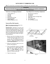
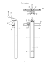
Guide Rail Assembly
1. Bolt the guide rail to the front rail with 1/4-20
x 3/4” hex cap screws 1/4" flat washers and
1/4" lock washers. Center the bolt heads in
the slotted holes of the rail so you will have
some lateral adjustment.
2. Measure from the front of the guide rail to
the front of the tablesaw table in a couple
spots to verify that the guide rail is parallel
to the table. Adjust as needed and tighten.
Fence Assembly and Adjustments
1. Thread the handle knob into the cam
assembly.
Note: Fence adjustments should be performed
in the order given.
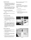
Level with the Saw Table
1. Place the fence on the table and lock it.
2. View the fence from the left side of the saw.
Look for the space between the table and
the fence bottom to be equal along the
entire length of the fence.
3. If adjustment is necessary, unlock the
fence.
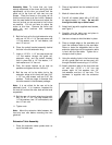
4. Raise or lower two nylon adjustment screws
(A,Fig.4)the same number of turns until
the space between the bottom of the fence
and the table is the same. Care must be
taken to raise or lower the fence on each
side equally or the fence may not be 90° to
the table after the height adjustment is
performed.
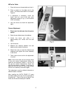
Parallel to the Miter Slot
1. Place the fence next to the outside edge of
the right miter slot and lock it.
2. The fence should be even with the miter slot
from front to back.
3. If the fence is not even along the length of
the miter slot, unlock the fence, remove it
and turn upside down.
4. Adjust one of the two set screws (A, Fig. 5)
until the fence is even with the miter slot
edge along its entire length when locked.
Note: You may need to re-adjust the clamping
pressure after aligning the fence.
Clamping Pressure
The XACTA FENCE II™ has been adjusted at
the factory to lock securely when the lock
handle is pushed down. If adjustment is
needed:
1. Unlock the fence.
2. Remove the fence from the guide rail.
3. Turn the fence over.
4. Adjust the two set screws (A, Fig. 5) until
the fence is held securely when the lock
handle is pushed down.