


4
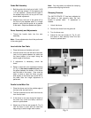
Assembly Note: To insure that you have
enough adjustment in the cursor during the final
adjustments, at this time you should bolt the
guide rail to the front rail with two hex cap
screws. Place the fence on the guide rail so
that the cursor lines up at four inches. Measure
from the saw blade to the fence and adjust the
front rail so that you are as close to four inches
as possible. You do not have to adjust the
cursor at this time. Remove the fence and
guide rail and continue with assembly
instructions.
5. Bolt the front rail to the right extension wing
with one 1/4”-20 x 1-1/4” hex cap screw, two
1/4” flat washer, one 1/4” lock washer, and
one 1/4” hex nut.
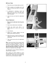
6. Place the switch bracket assembly behind
the hole in the left extension wing.
7. Insert a 1/4”-20 x 1-1/4” hex cap screw and
1/4" flat washer through the guide rail,
extension wing, and the switch bracket.
Hold in place with a 1/4" flat washer, 1/4"
lock washer and 1/4" hex nut.
8. Pushtheswitchbracketupashighas
possible and tighten the hex nut firmly.
9. Bolt the rear rail to the table (not to the
extension wings at this time) with two 5/16”
x 1/2” hex cap screws, and two 5/16” flat
washers. These are larger in diameter than
the other screws in the hardware package.
Note: It is not critical for the rear rail to be
absolutely level. It is, however, important for
the rear rail to clear the miter slots and be level
as possible.
10. Bolt the rear rail to each extension wing with
two 1/4”-20 x 1-1/4” hex cap screws, four
1/4” flat washers, two 1/4” lock washers, and
two 1/4” hex nuts.
11. Tighten nuts.
Note: Mount the extension table between the
front and rear rails before mounting the front
guide rail.
Extension Table Assembly
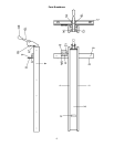
1. Place the extension table upside down on
top of the table saw.
2. Place a leg bracket into the outboard end of
the table.
3. Mark all holes to be drilled.
4. Pre-drill all marked holes with a 3/16” drill
bit approximately 1/2” deep. Do not drill
through the table top or table frame!
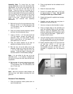
5. Attach both legs with supplied wood screws,
seeFigure3.
6. Carefully turn the table over and place in
between the front and rear rail.
7. Use two c-clamps to hold the table in place.
8. Place a straight edge on the saw table and
level the extension table to the saw table.
Raise or lower the adjustable feet on the
extension table legs until the extension table
is level with the saw table. Tighten the c-
clamps to hold in place.
9. Using the existing holes in the front and rear
rail as a guide (two front and two rear), drill
through the table frame using a 1/4” drill bit.
10. Attach extension table to the front and rear
rail with four 1/4”-20 x 1-1/4” hex cap
screws, eight 1/4” flat washers, four 1/4”
lock washers, and four 1/4” hex nuts. This
hardware is supplied with the extension
table.