


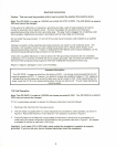
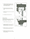

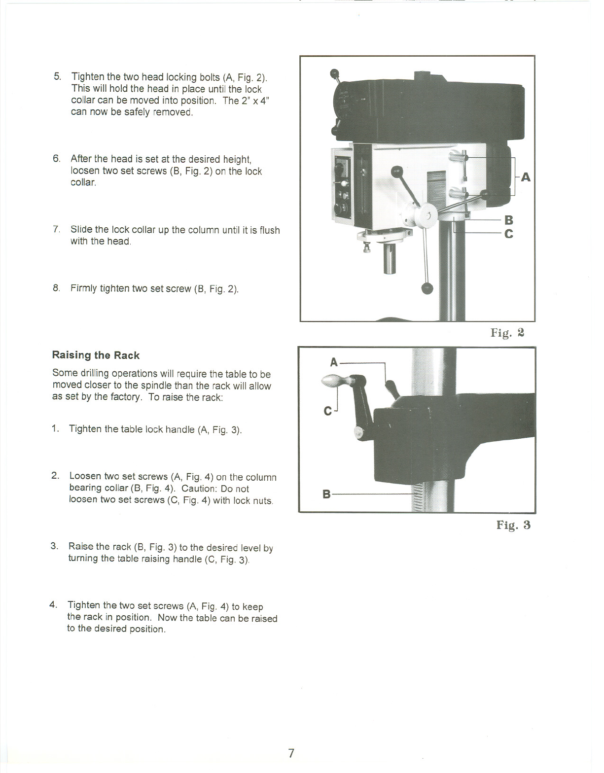
5. Tighten the two head locking bolts (A, Fig. 2).
This will hold the head in place until the lock
collar can be moved into position. The 2" x 4"
can now be safely removed.
6. After the head is set at the desired height,
loosen two set screws (8, Fig. 2) on the lock
collar.
7. Slide the lock collar up the column until it is flush
with the head.
8. Firmly tighten two set screw (8, Fig. 2).
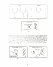
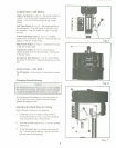
Raising the Rack
Some drilling operations will require the table to be
moved closer to the spindle than the rack will allow
as set by the factory. To raise the rack:
1. Tighten the table lock handle (A, Fig. 3).
2. Loosen two set screws (A, Fig. 4) on the column
bearing collar (8, Fig.4). Caution: Do not
loosen two set screws (C, Fig. 4) with lock nuts.
3. Raise the rack (8, Fig. 3) to the desired level by
turning the table raising handle (C, Fig. 3).
4. Tighten the two set screws (A, Fig. 4) to keep
the rack in position. Now the table can be raised
to the desired position.
B
C
Fig. 2
A
c
B
Fig. 3
7