


9
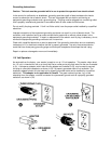
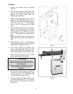
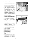
10. Sanding platen is presently in a horizontal
position. Pull lock handle forward (A, Fig. 3)
to unlock platen assembly, tilt sanding
platen to the vertical position, and push lock
handle to lock platen assembly in place.
Note: do not turn lock handle. Turning or
rotating the lock handle will change the
tension of the locking assembly. This may
cause the locking assembly not to work;
making it necessary for adjustment before
using the machine.
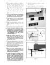
11. Remove the belt guards by unscrewing two
lock knobs (A, Fig. 4). Take out sanding
belt and fence from behind the belt guard.
12. Place handle (B, Fig. 4) on belt tensioning
shaft. Take tension off the mechanism by
moving the handle to the left.
13. Make sure that direction arrow on belt
matches direction indicator on the belt
cover.
14. Place belt on both rollers so that the edge of
the belt is even with the edge of the rollers.
15. Tension the belt by moving the tension
handle lever (B, Fig. 4) to the right. Rotate
the belt by hand in the direction indicated by
the arrow on the belt guard. If belt tracking
needs adjustment, see “Belt Tracking
Adjustment” pages 11-12.
16. Attach the extension bracket (A, Fig. 5)
using three hex cap bolts, three lock
washers and three flat washers (B, Fig. 5).
The hardware can be found in the bag with
the 3mm Hex Wrench.
17. Fasten the extension table (C, Fig. 5) to the
support rod (D, Fig. 5) by tightening the hex
cap screw (E, Fig. 5) against the flat on the
support rod. Tighten the jam nut.
18. Raise the table to a good height and tighten
two set screws on the bracket.
19. Mount the small bracket between the
backside of the extension bracket and the
sander using two hex cap bolts, two lock
washers and two flat washers.
20. Connect the sander to the power source,
turn on the power to the machine just
enough to start the belt rotating and then
turn off. Do this several times and observe
belt tracking. The belt should not wander up
or down. It should be centered between the
two belt rollers. If adjust is necessary refer
to “Belt Tracking Adjustment” pages 11-12.
21. Reinstall the guards and secure in place
with lock knobs.
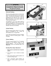
22. Attach the extension cover (D, Fig. 6) with
three pan head screws and one lock knob.