


14
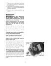
Material chips or shavings are the best indicator
of proper blade speed and downfeed rate. The
ideal chip is thin, tightly curled and warm to the
touch. Chips that range from golden brown to
black indicate excessive force. Blue chips
indicate extreme heat from too high a blade
speed, which will shorten blade life. Thin or
powdered chips indicate insufficient downfeed
rate.
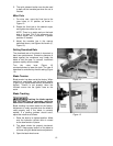
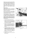
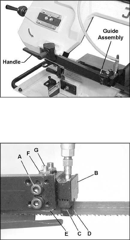
Blade Guides
Loosen the handle (Figure 17) and slide the
guide assembly as close to the workpiece as
possible. This will prevent excessive exposure
of the blade during operation.
[NOTE: The handle (Figure 17) can be adjusted
out of the way. Lift up on the handle and rotate it
on the pin. Release the handle, making sure it
seats itself properly on the pin.]
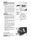
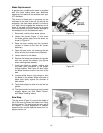
The guide bearings and carbide guide blocks
come pre-adjusted from the factory, but should
be inspected frequently and adjustments made
as needed. For most efficient operation and
maximum accuracy, provide 0.001” clearance
between the blade and the guide bearings. The
bearings will still turn freely with this clearance.
If the clearance is incorrect, the blade may track
off the drive wheel.
1. Disconnect machine from power source.
2. Loosen the two socket head cap screws (A,
Figure 18) and move the guide seat (B,
Figure 18) up or down until the guide blocks
(D, Figure 18) are positioned adequately
across the width of the blade.
3. Loosen the socket head cap screws (C,
Figure 18) on the carbide guide blocks (D,
Figure 18) and shift both guide blocks until
they place a light pressure on the blade. Re-
tighten the socket head cap screws (C,
Figure 18).
4. The outer guide bearing (E, Figure 18) is
mounted to an eccentric bushing and is
adjustable. Loosen the hex nut (F, Figure
18) and rotate the bearing shaft (G, Figure
18) with a wrench until the bearing (E,
Figure 18) clears the blade by
approximately .001”. Do not pinch the blade.
5. Re-tighten hex nut (F, Figure 18).
6. Repeat these steps for the other blade
guide assembly.
Figure 17
Figure 18