


1
4
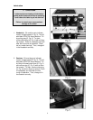
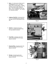
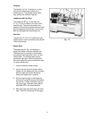
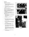
Tailstock
The tailstock (A, Fig. 12) slides on a v-way
and can be locked at any location by a
clamping lever. The tailstock has a heavy
duty spindle with a Morse Taper #3.
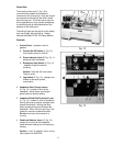
Leadscrew and Feed Rod
The leadscrew (B Fig. 12) and feed rod
(C, Fig. 12) are mounted on the front of the
machine bed. They are connected to the
gearbox at the left for automatic feed and lead,
and are supported by bushings on both ends.
Both are equipped with brass shear pins.
Gear Box
The gear box (D, Fig. 12) is made from high
quality cast iron and is mounted to the left side
of the machine bed.
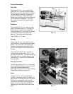
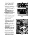
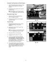
Steady Rest
The steady rest (E, Fig. 12) serves as a
support for shafts on the free tailstock end.
The steady rest is mounted on the bedway
and secured from below with a bolt, nut and
locking plate. The sliding fingers require
continuous lubrication at the contact points
with the workpiece to prevent premature wear.
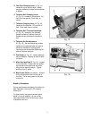
To set the steady rest:
1. Loosen three hex socket screws.
2. Loosen knurled screw and open sliding
fingers until the steady rest can be moved
with its fingers around the workpiece.
Secure the steady rest in position.
3. Set the fingers snugly to the workpiece
and secure by tightening three hex socket
cap screws. Fingers should be snug but
not overly tight. Lubricate sliding points
with Mobil DTE Oil Heavy Medium.
4. After prolonged use, the fingers will show
wear. Remill or file the tips of the fingers.