


Hand Carry Electric Air Compressor Manual 9
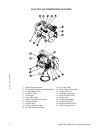
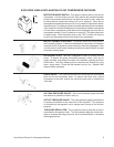
EXPLODED VIEW & EXPLANATION OF AIR COMPRESSOR FEATURES
AIR TANK PRESSURE GAUGE: The air tank pressure gauge indicates
the reserve air pressure in the air tank (s).
OUTLET PRESSURE GAUGE: The outlet pressure gauge indicates the
air pressure available at the outlet side of the regulator. This pressure
is controlled by the regulator and is always less or equal to the air tank
pressure.
PRESSURE REGULATOR: The air pressure coming from the air tank is
controlled by the regulator knob. Turn the pressure regulation knob clock-
wise to increase discharge pressure, and counterclockwise to decrease
discharge pressure.
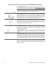
MOTOR THERMAL OVERLOAD: The electric motor has a manual ther
-
mal overload protector. If the motor overheats for any reason, the thermal
overload will cut off power to prevent the motor from being damaged. Wait
until the motor is cool before pressing the thermal overload button to reset
and begin working again.
MOTOR/PRESSURE SWITCH: This switch is used to start or stop the air
compressor. Pull the switch up to the "ON" position will provide automatic
power to the pressure switch which will allow the motor to start when the
air tank pressure is below the factory set "cut-in" pressure. When the air
tank pressure reaches the factory set "cut-out" pressure, the pressure switch
stops the motor. For safety purposes, this switch also has a pressure release
valve located in the switch designed to automatically release compressed
air from the air compressor pump head and its discharge line when the air
compressor reaches "cut-out" pressure or is shut off. This allows the motor
to restart freely. Push the switch down to the "OFF" position will remove
power from the pressure switch and stop the air compressor.
AIR INTAKE FILTER: This filter is designed to clean air coming into the
pump. To ensure the pump continually receives a clean, cool, dry air
supply this filter must always be clean and ventilation opening free from
obstructions. The filter element can be removed and cleaned by using
warm, soapy water. Rinse the filter element and air dry. Replace filter
element when necessary.
CHECK VALVE: This valve prevents the air tank pressure from flowing
back into the air compressor head. To inspect the check valve, relieve
all pressure in the tank, remove the valve plug and clean or replace the
valve disc.
8
8
10
11
18