


Portable Gasoline Air Compressor Manual 9
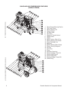
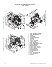
EXPLODED VIEW & EXPLANATION OF AIR COMPRESSOR FEATURES
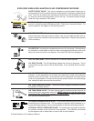
SAFETY RELIEF VALVE: This valve is designed to prevent system failures by re-
lieving pressure from the system when the compressed air reaches a predetermined
level. The valve is preset by the manufacturer and must not be modified in any way.
To verify the valve is working properly, pull on the ring. Air pressure should escape.
When the ring is released, it will reseat.
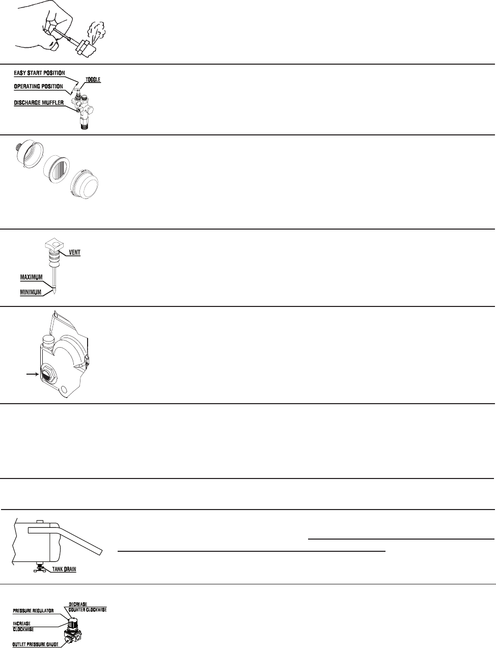
PILOT VALVE: When the toggle is in the horizontal position, all air from the air com
-
pressor is vented through the discharge muffler. This gives an easy start feature. For
normal operation, the toggle is in the vertical position.
AIR INTAKE FILTER: This filter is designed to clean air coming into the pump. To
ensure the pump continually receives a clean, cool, dry air supply this filter must al-
ways be clean and ventilation opening free from obstructions. Replace filter element
when necessary.
OIL DIPSTICK: The dipstick will register the amount of oil in the pump. Oil level should
be checked on a daily basis to ensure it does not exceed the maximum notch or fall
below the minimum notch on the dipstick. If low, add SAE 30W non-detergent oil.
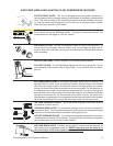
OIL FILL PORT/VENT: Pour oil into the Oil Fill Port/Vent when required.
OIL SIGHT GLASS: The Oil Sight Glass displays the oil level in the pump. The oil
level should be at the center of the Oil Sight Glass. If low, add SAE 30W non-deter
-
gent oil.
AIR COMPRESSOR PUMP: To compress air, the pistons move up and down in the
cylinders. On the downstroke, air is drawn in through the air intake valves while the
exhaust valves remain closed. On the upstroke, air is compressed, the intake valves
close and compressed air is forced out through the exhaust valves, into the discharge
line, through the pilot valve and into the air tank.
AIR TANK PRESSURE GAUGE: The air tank pressure gauge indicates the reserve
air pressure in the air tank (s).
AIR TANK DRAIN VALVE: The drain valve is used to remove moisture from the air
tank(s) after the air compressor is shut off. NEVER attempt to open the drain valve
when more than 10 PSI of air pressure is in the air tank! To open the drain valve,
turn the knob counterclockwise.
OPTIONAL PRESSURE REGULATOR: The air pressure coming from the air tank is
controlled by the regulator knob. Turn the pressure regulation knob clockwise to in
-
crease discharge pressure, and counterclockwise to decrease discharge pressure.
OPTIONAL OUTLET PRESSURE GAUGE: The outlet pressure gauge indicates the
air pressure available at the outlet side of the regulator. This pressure is controlled
by the regulator and is always less or equal to the air tank pressure.
1. Decal: Danger/Warning/Caution
2. Tank Drain Valves
3. Decal- Warning: Hot
4. Pump Oil Drain
5. Oil Sight Glass
6. Pilot Valve
7. Engine Air Throttle Control
8. Engine Switch
9. Engine
10. Decal- Caution: Risk of Fire
11. Decal- Warning: Hot Surface
12. Pump Discharge Line
13. Beltguard
14. Decal- Warning: Risk of Injury
15. Decal- Warning: Beltguard
16. Air Filter
17. Oil Fill Port
18. Pump
19. Ventilation Openings
20. Pressure Gauge - Tank PSI
21. Pressure Relief Valve
22. Pressure Regulator
23. Pressure Gauge - Outlet PSI
24. Outlet Fitting