


Operator’s Manual 21
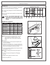
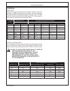
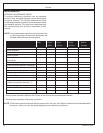
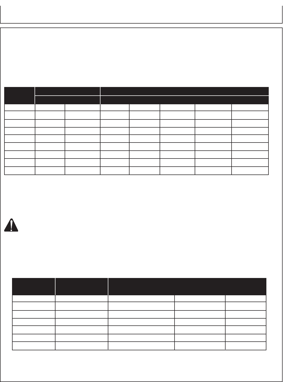
CURRENT LOAD IN WATTS MAXIMUM CABLE LENGTH (FEET)
IN AMPS 120 VOLTS 240 VOLTS #8 WIRE #10 WIRE #12 WIRE #14 WIRE #16 WIRE
2.5 300 600 1000 600 375 250
5 600 1200 500 300 200 125
7.5 900 1800 350 200 125 100
10 1200 2400 250 150 100 50
15 1800 3600 150 100 65
20 2400 4800 175 125 75 50
25 3000 6000 150 100 60
30 3600 7200 125 65
40 4800 9600 90
Operating the Generator
CONTROLS
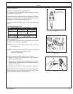
CABLE SIZE:
Equipment damage can result from low voltage. Therefore, to prevent
excessive voltage drop between the generator and the equipment,
the cable should be of adequate gauge for the length used. The cable
selection chart gives the maximum cable lengths for various gauges of
wire which can adequately carry the loads shown.
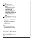
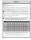
ELECTRIC MOTOR LOADS:
It is characteristic of common electric motors in normal operation to draw
up to six times their running current while starting. This table may be
used to estimate the watts required to start “CODE G” electric motors.
CAUTION: IF AN ELECTRIC MOTOR FAILS TO START OR
REACH RUNNING SPEED, TURN OFF THE
APPLIANCE OR TOOL IMMEDIATELY TO AVOID
EQUIPMENT DAMAGE. ALWAYS CHECK THE
REQUIREMENTS OF THE TOOL OR APPLIANCE
BEING USED COMPARED TO THE RATED OUTPUT
OF THE GENERATOR.
WATTS REQUIRED TO START MOTOR
MOTOR (H.P.) RUNNING WATTS REPULSION INDUCTION CAPACITOR SPLIT PHASE
1/8 275 600 850 1200
1/6 275 600 850 2050
1/4 400 850 1050 2400
1/3 450 975 1350 2700
1/2 600 1300 1800 3600
3/4 850 1900 2600
1 1100 2500 3300