


- 3
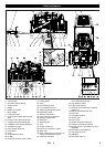
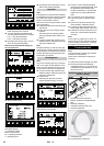
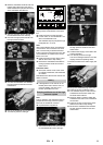
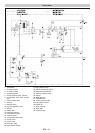
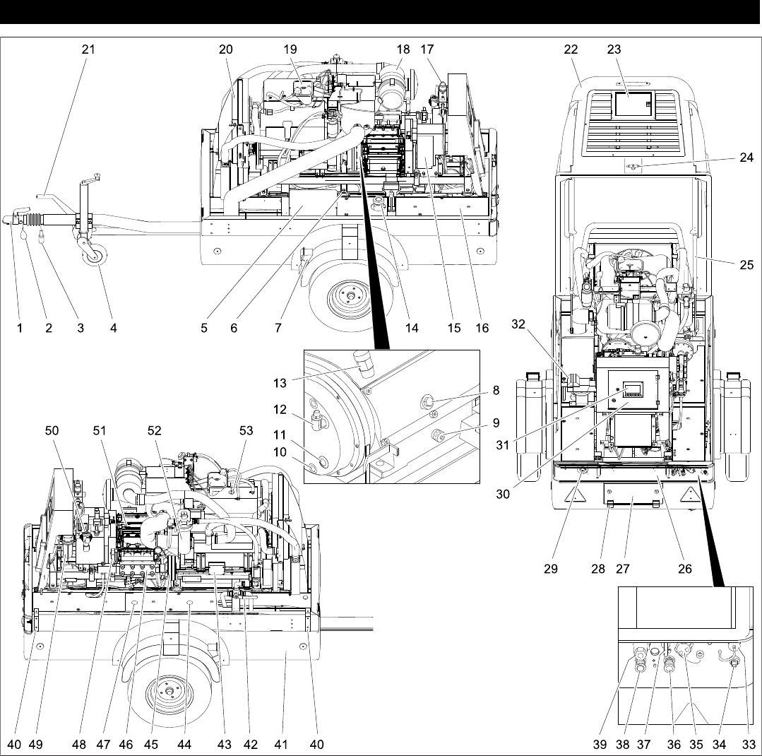
1 Towing hitch
2 Tear-off rope
3 Connector vehicle lighting
4 Support wheel
5 Battery
6 Battery main switch
7 Block wedge
8 Oil dip pump gear
9 Covering lid, oil drain opening pump
gear
10 Oil drain screw intermediate gear
11 Oil sight glass intermediate gear
12 Ventilation screw intermediate gear
13 Ventilation end gear
14 Filling nozzle diesel tank
15 Compressor
16 Cover
17 Compressed air valve
18 Air filter
19 Equalising reservoir motor coolant
20 Radiator
21 Parking brake
22 Cover
23 Door operating panel
24 Lock of appliance hood
25 Safety support appliance hood
26 Registration plates
27 Storage compartment
28 Hinge, storage compartment
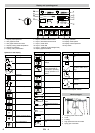
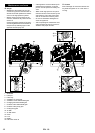
29 Emergency-stop button
30 Switch box
31 Operating field
32 Vice
33 Socket, control line
34 Exterior air connection (supply)
35 Water inlet
36 Right compressed air connection, to
connect a compressed air tool
37 Hose sock mounting
38 Left compressed air connection, to con-
nect a compressed air tool
39 High-pressure outlet
40 Lifting eyelet (option)
41 Drain tap of the water tank (inside the
appliance)
42 Ball tap, antifreeze/water tank
43 Main fuse
44 Antifreeze container
45 Switch valve
46 Pump head
47 Maintenance door water tank
48 Pressure sensor/high pressure
49 Maintenance unit, pneumatics (cyclone
separator)
50 Manometer compressed air
51 High pressure pump
52 Waterfilter
53 Filler neck motor oil
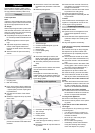
Device elements
5EN