


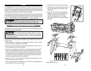
6. Repeat this step for the remaining three legs.
7. Position the floor stand handle in the holes on
the front legs. Adjust the legs slightly so the
handle will fit.
8. Using two 1/2" (12 mm) box-end wrenches,
place one on the hex nut on the inside of the
attached leg and one on the outside hex
screw head. Holding the hex nut in place,
securely tighten the four screws attaching the
front legs.
14
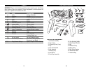
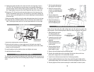
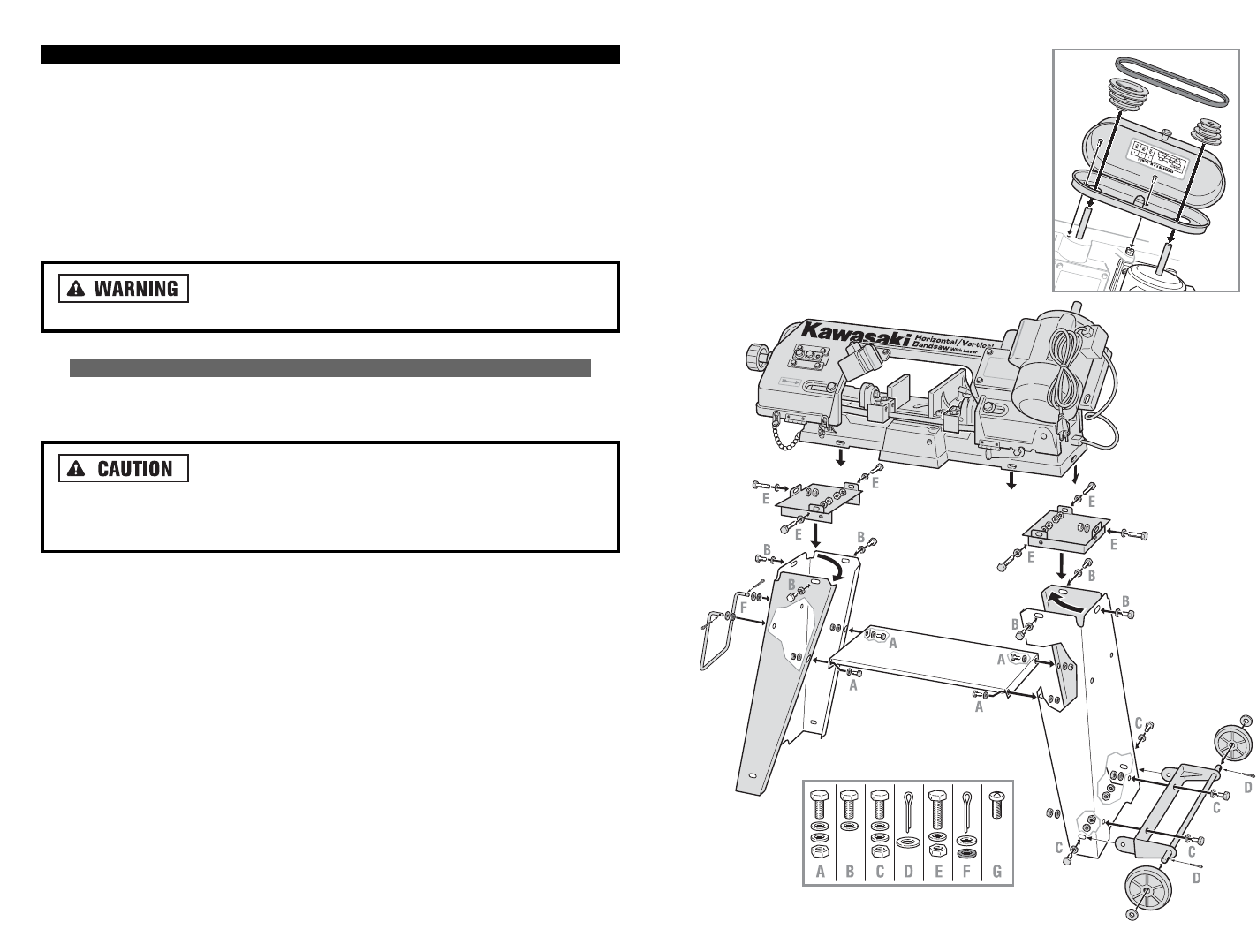
ASSEMBLY
The KAWASAKI™ Horizontal /Vertical Metal Cutting Band saw requires very little
assembly. The band saw head and motor assemblies are assembled and adjusted at
the factory. The assembly includes attaching the stand legs to the band saw base
and attaching the adjustment wheels to their proper spindles.
Before beginning the assembly, carefully unpack the band saw and all included parts
and accessories. Visually inspect all items for damage. Should anything be broken
or bent, DO NOT attempt to assemble the band saw. Contact Alltrade Customer
Service at 1-800-590-3723 (toll free) IMMEDIATELY for replacement parts.
DO NOT connect the band saw to the AC power source until
tool is completely assembled and adjusted per instructions in this manual.
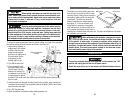
ATTACHING THE LEGS TO THE BAND SAW BASE
Attaching the legs to the metal cutting band saw also includes attaching the wheel
assembly and the floor stand handle.
The metal cutting band saw weighs ± 60 lbs (± 27 kg). The
band saw and base unit will need to be positioned on its side for various assem-
bly procedures. It is recommended that two people be used to position the band
saw for these assemblies.
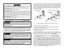
Proceed with the following steps to assemble the legs, wheels and floor stand han-
dle. See Figure 2.
1. Place a large piece of cardboard or other protective material on the floor so the
band saw will not be damaged during assembly.
2. Using two people, carefully place the band saw and base unit so that it rest on
the bow assembly and the motor assembly.
3. Place one of the metal legs in the inside corner and align the two holes. NOTE:
There are two legs with mounting holes several inches below the holes that
attach the legs to the base. The legs should be on the opposite end of the base
from where the motor is mounted (the front of the band saw). The remaining
tow legs have holes near the bottom. These legs mount under the end where
the motor is mounted (the rear of the band saw).
4. Insert a 1/4" X 20 X 1 1/4" hex head screw through each of the two holes in the
base and through the holes in the leg.
5. Insert a washer on the screw followed by a 1/4" X 20 hex nut. Finger-tighten the
screws at this time. Do not use any tools.
G
FIGURE 2.
ASSEMBLING THE BAND SAW
13