


18
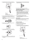
7. Use a 7 mm socket and wrench or 7 mm nut driver to install
the new 2.01 mm (inner burner) and 2.87 mm (outer burner)
brass orifices supplied with this kit.
NOTE: The number 2.01 and 2.87 are stamped on the orifices
for identification.
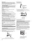
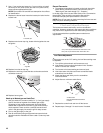
8. Replace the burner base. Insure the locator pin locks into the
locator hole.
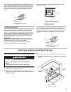
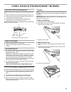
9. Replace outer burner top ring, locate with the igniter slot over
the igniter.
10. Replace inner burner top ring.
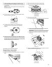
11. Replace the wok ring, locate the tabs to the slots and twist
clockwise to secure.
12. Replace burner grate.
Hook up to Natural gas and Leak Test
1. Use pipe wrench to connect certified ¹⁄₂" (1.3 cm) gas supply
pipe to inlet side of regulator from Natural gas supply
according to local codes requirements. Use pipe thread
sealant that is certified for use with LP gas at connections
where required. There must be a certified manual shutoff
valve in the gas supply line near the grill for easy access.
2. Turn on the gas supply to the grill.
3. Test all connections using an approved noncorrosive leak-
detection solution. Bubbles will show a leak. Correct any leak
found.
Record Conversion
1. The appliance nameplate is located on the right-hand side
panel. With a permanent marker, check the box next to
“Natural gas” and mark through “LP - Propane.”
In the last page of the Use and Care Guide, write “Converted to
Natural Gas.” Also record the conversion date and the
technician/company that performed the conversion.
NOTE: Place LP gas parts in plastic parts bag for future use and
keep with pack containing literature.
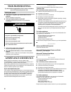
Check and Adjust the Burners
The burners are tested and factory-set for most efficient
operation. However, variations in gas supply and other conditions
may make minor adjustments to low flame setting necessary.
It is recommended that a qualified person make burner
adjustments.
Low Flame Adjustment
If flame goes out on the “LO” setting, the low flame setting must
be adjusted.
1. Turn off the valve and wait until burners are cool.
2. Light Power™ burner using information in the “Outdoor
Power™ Burner Use” section.
3. Turn burner to its lowest setting and remove knob.
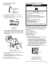
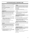
4. Hold valve stem with pliers and insert a small flat-blade
screwdriver into the shaft.
5. Watch the flame and slowly turn the screwdriver
counterclockwise.
6. Adjust flame to minimum stable flame.
7. Replace the control knob and turn off the burner.
8. Repeat steps 3 through 7 for each burner if needed.
A.Locator pin
A.Igniter
A
A
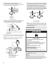
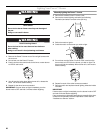
A.4" (10.2 cm) for outer burner when set to “HI.”
B.3" (7.6 cm) for inner burner when set to HI.”
A.Valve stem
B.Small flat-blade screwdriver
C.Pliers
A
B
A
B
C