12
SECTION 2 INSTALLATION
D. Check all connections for proper tightness. En-
sure all connections are correct and well insu-
lated.
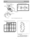
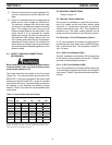
E. Figure 2-2 illustrates the input voltage terminal
board and the input voltage link connections.
The particular voltages from which this power
source may be operated are stated on the rating
plate. The voltage links were factory set for
highest voltage stated on the rating plate. If the
power source is to be operated on another
stated input voltage, the links must be reset for
that particular input voltage. Always verify the
input voltage and check the link arrangement
regardless of factory setting. The voltage links
are set up by re-configuring the copper link bars
to the silk screened voltage designations for the
desired voltage.
2.4 OUTPUT WELDING CONNECTIONS
(SECONDARY)
Before making any connections to the power source
output terminals, make sure that all primary input
power to the machine is off.
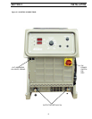
The output terminals are located on the front panel
(Figure 2.3). Two output terminals are provided. One
NEGATIVE (-) terminal is located at the bottom right
hand corner and the POSITIVE (+) terminal is located
at the bottom left corner. The output cable connections
will depend on the materials and welding process
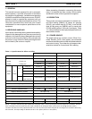
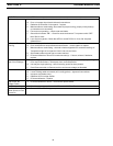
desired. Table 2-2 provides the recommended cable
output sizes.
Table 2-2. Output Cable Sizes (Secondary)
2.5 CONTROL CONNECTIONS
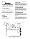
Refer to Figure 2-3.
2.5.1 Remote Control (Optional)
This function is provided by an optional 14-pin recep-
tacle (J2) located on the front panel directly below
connector J1. It mates with a plug from any optional
remote control device (see 1.4.2). This receptacle is
operative only if the panel remote switches on the
power source front panel are in the "Remote" position.
2.5.2 Auxiliary 115 V AC Receptacle (Option)
A 115 Vac receptacle is provided to supply power to
accessories such as a water cooler, heated C02 regu-
lator, or small hand tools. The receptacle is rated 115
Vac / 10 amps.
2.5.3 - 42V Circuit Breaker (CB1)
The 42V resettable circuit breaker (CB1) protects the
42 volt control circuitry against over current. (Table 52
provides troubleshooting information).
2.5.4 - 115V Circuit Breaker (CB2)
The 115V resettable circuit breaker (CB2) protects the
115 volt auxiliary receptacle and control circuitry against
over current. (Table 5-2 provides troubleshooting infor-
mation).
Welding
Current 50 100 150 200 250
10064321/0
150 4 3 1 1/0 2/0
200 3 1 1/0 2/0 3/0
250 2 1/0 2/0 3/0 4/0
300 1/0 2/0 3/0 4/0 4/0
400 2/0 3/0 4/0 4/0 2-2/0
500 3/0 3/0 4/0 2-2/0 2-3/0
Total Length (Feet) of Cable In Weld Circuit*
*Total cable length includes work and electrode cables. Cable size is based on direct
current, insulated copper conductors, 100 percent duty cycle and a voltage drop of 4 or
less volts. The welding cable insulator must have a voltage rating that is high enough
to withstand the open circuit voltage of the machine.


