14
Never operate the power source with the cover re
moved. In addition to the safety hazards, lmproper
cooling may cause damage to the components.
Keep side panels closed when unit is energized.
Welding helmet, gloves, and other personal protec-
tion should always be worn when welding.
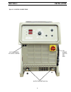
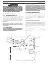
3.1 CONTROLS (See Figure 3.1)
3.1.1 PowerSwitch(ON-OFF)/(I-O)
The power switch is located on the front panel of the
power source. In the OFF ("0") position, the unit is
shutdown however, power is still present at the switch
itself. To totally shut down the power source, power
must be disconnected at the line disconnect switch or
the fuse box.
With the switch in the ON ("I") position, power is
provided to the main transformer and the low voltage
control circuitry.
3.1.1.1 Power Indicator
This white light will indicate that the power switch is in
the ON position and power has been applied to the main
transformer and low voltage circuitry.
3.1.2 Arc Force Control.
This control is used for stick welding only.The lower
settings provide less short circuit current and a softer,
more stable arc. The higher settings provide more short
circuit current and a forceful, more penetrating arc. For
most Stick welding, set the knob at 3 or 4 and readjust
up (forceful) or down (softer) as desired.
3.1.3 Contactor, On/Remote Switch
The Contactor Control switch is located on the front
panel of the power source. In the ON position, the solid
state contactor is energized and output power is avail-
able at the output terminals. The REMOTE position
allows the solid state contactor to be controlled from a
remote control.
3.1.4 Current Panel/Remote Switch
With this switch in the PANEL position, output current
is controlled by adjusting the potentiometer on the front
panel to the desired output. In the REMOTE position,
output is controlled using an optional remote control via
receptacle J2.
3.1.5 Current Control
This control allows the operator to adjust the output
current. Placing the Panel/Remote switch in the RE-
MOTE position disables the current control on the front
panel.
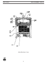
Figure 3.1 Control Locations (453cc illustrated)
3.1.1.1
3.1.6
3.1.8
3.1.7
3.1.5
3.1.4
3.1.3
3.1.2
3.1.1
SECTION 3 OPERATION


