


15
3.1.6 Over Temperature Indicator (Temp)
This amber light will indicate when an internal overheat-
ing condition has occurred and one of the thermal
switches has opened. User control of the solid state
contactor will be interrupted and power source output
will shut down to protect critical components. Once
cooled to a safe temperature, the thermal switch will
automatically reset and output control will be restored.
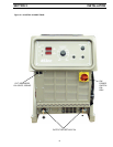
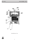
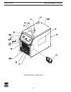
3.1.7 Voltmeter and Ammeter
A digital voltmeter and ammeter provides an accurate
indication of dc output voltage and current.
3.1.8 Fault Indicator
If an optional External Ground Conductor Protection Kit
was installed, this red light, when lit, will indicate that
current was flowing through the external ground con-
ductor. The power source output termirals are
deenergized and the fault must be corrected before
resuming operation.
3.2 OPERATION SET-UP
Prior to performing the steps below, open the wall
disconnect switch or remove the fuse from the fuse box
to electrically isolate the power source.
ELECTRIC SHOCK CAN KILL! "Machinery Lockout
Procedures" should be employed. If it is not pos-
sible to use padlocks, attach a red tag to the line
disconnect switch (or fuse box) warning others
that the circuit is being worked on.
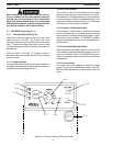
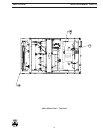
3.2.1 Stick Welding (SMAW) Air Carbon Arc Goug-
ing (ACAG) and Scratch Start Tig Welding
(GTAW)
A. If stick welding or arc gouging, connect work
cable to the workpiece and to the negative (-)
terminal of the power source. Connect torch
cable to the positive (+) terminal of the power
source.
If Tig welding, connect work cable to the
workpiece and to the positive (+) terminal of the
power source. Connect Tig torch cable to the
negative(-) terminal of the power source.
B. Place the Power ON-OFF switch to the ON
position or close the main(wall) disconnect
switch.
C. Adjust the current control on the power source
to the approximate desired welding current.
D. If stick welding, set the Arc Force control at 3 or
4 on the dial and readjust as necessary to obtain
a softer or harder welding arc.
For air gouging or Tig welding, set Arc Force
control at zero (0).
E. If using a remote current control, such as HC-
3B, place current and contactor switches in
REMOTE positions. Note that the current range
will be limited to the maximum setting on the
power source's current control dial.
If not using remote current control, place current
switch to PANEL and contactor switch to ON.
F. Place the Power ON-OFF switch to the ON
position.
G. To preset the approximate welding current, pro-
ceed as follows:
1. Connect the electrode holder to the
workpiece to create short.
2. Place the contactor switch to the ON posi-
tion.
3. Set the Arc Force control to the minimum
position.
4. Place the Power On-Off switch to the ON
position.
5. By observing the digital ammeter,adjust
Current Control to the desired current set-
ting.
6. Place Power On-Off switch back to OFF
7. Then remove the holder from the work-
place.
H. After setting the desired current and if using
remote, turn switch back to REMOTE.
I. You are now ready to begin welding.
3.2.2 Mig Spray Am (GMAW) and Flux Cored
(FCAW) Welding with "Off the Are" Wire
Feeder.
Refer to wire feeder instruction manual for set-up and
operating procedures.
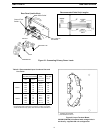
SECTION 3 OPERATION