


17
5.1 GENERAL
DISCONNECT primary power at wall switch, or
circuit breaker, before attempting inspection or
work inside the power source.
If the power source is operating improperly, the follow-
ing troubleshooting information may be used to locate
the source of the trouble.
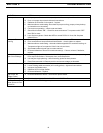
Check the problem against the symptoms in the follow-
ing troubleshooting guide (Table 5-2.) The remedy for
the problem may be quite simple. If the cause cannot be
quickly located, open up the unit and perform a simple
visual inspection of all the components and wiring.
Check for proper terminal connections, loose or burned
wiring or components, blown fuses, bulged or leaking
capacitors, or any other sign of damage or discolora-
tion.
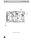
5.2 TESTING AND REPLACING BRIDGE ASSEM-
BLY COMPONENTS
The SCRs used in the power source are devices which
allow current to flow in only one direction. The SCRs are
designed to provide long trouble-free operation; how-
ever, should a failure occur, they may require replace-
ment.
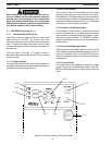
A. Testing SCRs.
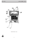
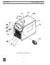
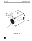
1. Remove top and right side panel from the power
source.
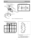
2. Locate the main rectifier assembly containing
the SCRs.
3. Electrically isolate main bridge assembly by
disconnecting resistor R5.
4. With the ohmmeter on RX1 scale, place the
positive lead on the anode (end of SCR with
screw threads) and the negative lead on the
cathode (positive output terminal on the front
panel). The meter should read minimum of 5
megohms.
5. Reverse leads and check each SCR. All read-
ings should again show high resistance. The
SCRs are bad if they show low resistance in
either direction.
6. Check the gate circuit on the SCRs by installing
a jumper from the gate lead to the anode of the
SCR. The meter should read less than 5 ohms.
Remove the jumper from the gate. The meter
reading should increase (3050 ohms).
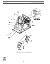
B. Replacing the SCRs.
IMPORTANT
1. When replacing SCR’s, make sure mounting
surfaces are clean. Using Alcoa No. 2 EJC
Electrical Joint Compound or an equivalent,
apply a thin coat to the SCR mounting surface
and positively locate in place on the heatsinks.
Place the clamp in position with the bolts through
the holes in the heatsinks and proceed as fol-
lows:
2. Tighten the bolts evenly until finger tight noting
that the nuts are not rotating.
3. Tighten the bolts 3/4 turn plus an 1/8 turn using
a socket wrench on the bolt heads and rotating
only in 1/4 turn increments plus 1/8 turn alternat-
ing between the bolts noting that the nuts are not
rotating.
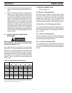
5.3 PCB VOLTAGE TESTS
Electrical service and repair should be attempted
only by a trained electrician.
When making PCB voltage measurements, refer to the
schematic diagram. All voltage readings are taken with
the front access panel open and the power switch “ON”.
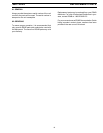
Table 5.1 SCR Voltages (Output)
FROM TO READING
P8-5 OTB+ +10 V dc
P8-7 OTB+ 0-10 V dc*
P6-6 (SCRI)
P6-5 (SCR2)
P6-4 (SCR3)
P6-3 (SCR4) OTB+ .3 V dc with
P6-2 (SCR5) contactor on
P6-1 (SCR6)
* Varies with setting of VCP (R1)
SECTION 5 TROUBLESHOOTING