


ACCESSORIES - FILL CUP EXTENSION KIT(S)
1. The SGH humidifier is an electrode humidifier.
It produces steam at atmospheric pressure.
Pressure head must develop to push steam
through supply line and into air duct.
2. Combined resistance of duct positive static
pressure and steam line resistance creates a
small pressure head in steam cylinder. Total
amount of positive static pressure head is
reflected directly by water column differential
that develops between water in the fill cup
hose feeding cylinder and water level in
cylinder.
3. Standard dimensions of humidifier limit static
that can be tolerated before water will be
pushed high enough to spill over into overflow
tube in fill cup assembly.
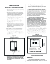
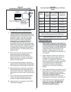
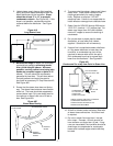
4. To increase allowable water column (allowable
positive static pressure) an accessory Fill Cup
Extension Kit is available from Liebert. See
Figure #22.
CONDENSATE RETURN LINE
1. Each steam distributor has a built-in
condensate return (3/8" O.D. copper tubing).
Flexible condensate return hose (3/8" I.D.)
available from Liebert, is recommended for
routing condensate back into humidifier’s fill
cup. Note: A short length of 3/8" O.D. copper
tubing is supplied by Liebert for use when
routing condensate hose back to humidifier’s
fill cup. Similarly, a short length of 3/8" I.D.
condensate hose with clamps is supplied with
Liebert’s steam distributors to serve as a
flexible coupling. DO NOT direct solder field
copper condensate line to steam distributors.
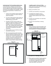
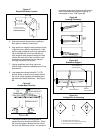
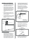
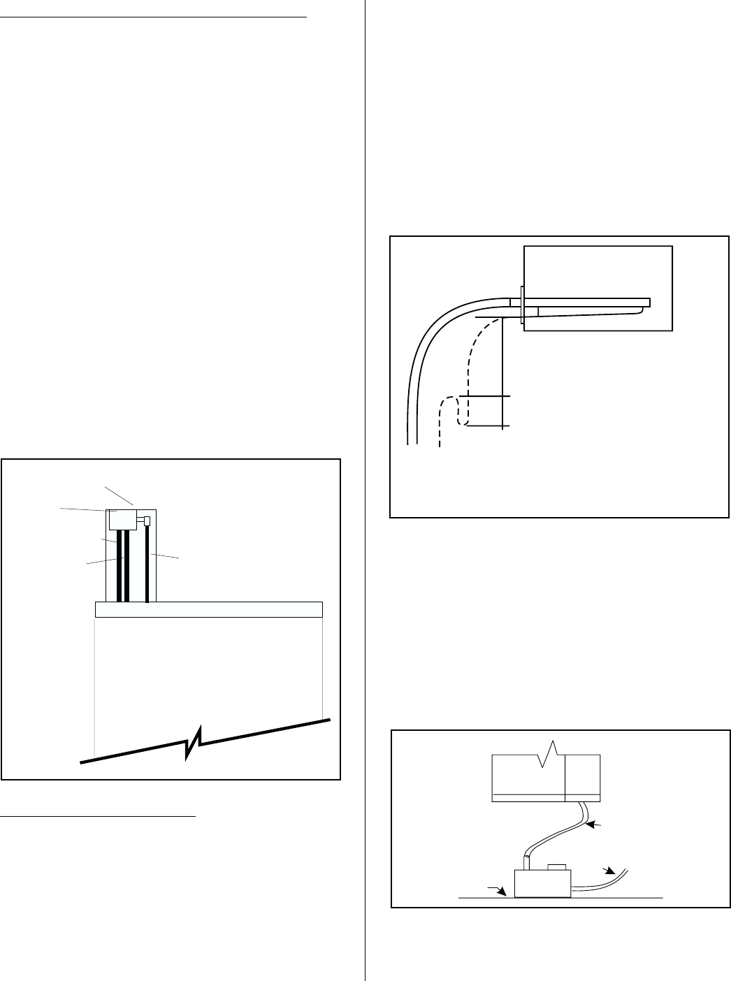
2. Always incorporate a trap in routing of
condensate return line. Condensate that
accumulates in trap will prevent possibility of
steam escaping. Depth of trap must exceed
duct static pressure by 2 inches of water
column. See Figure #23.
3. Condensate return line can not be run back to
fill cup if humidifier is within 36" of being level
with steam distributor. See Figure #18.
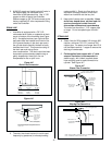
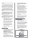
4. If steam distributor is mounted level with or
below humidifier, condensate line must be
routed to nearest floor drain or to a
condensate pump (available from Liebert).
See Figure #24.
5. Provide a “U” trap in condensate line even
when distributor is located in return air
plenum. It stops a suction action from
-8-
TRAP
3 FEET MINIMUM
CONDENSATE TRAP
DEPTH OF TRAP
MUST BE 2" MORE THAN
DUCT STATIC PRESSURE
OF WATER COLUMN
Figure #23
Trap to Prevent Steam in Condensate Line
HOSEFROMFILLVALVE
FILLCUP BRACKET
FILLCUP
OVERFLOWHOSE
FILLHOSE TO
CYLINDER
Figure #22
Fill Cup Extension Kit to Overcome Static Pressure
Humidifier
Drain Line
Drain
Pump
Floor
Surface
Line
Figure #24
Drain Pump (if necessary)