


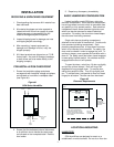
5. ALWAYS supply and install a shut off valve in
the water supply line dedicated to the
humidifier to facilitate servicing. Use ½"OD
copper to within 4 feet of the humidifier.
Reduce copper to 3/8" OD and connect to the
factory-supplied 3/8" olive compression fitting
under the humidifier.
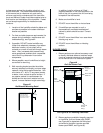
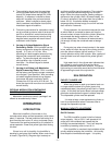
DRAIN LINE
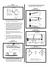
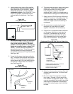
1. Humidifier is equipped with a 7/8" O.D.
unthreaded drain outlet on underside of drain
canal on bottom of the humidifier (see Figure
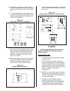
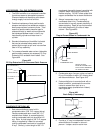
#15). A supplied reducer (see Figure #16)or
equivalent shall be installed on the drain line.
It will prevent backup in the drain pan and in
the cylinder due to partially blocked or badly
installed drain lines. This prevents rusting of
the drain pan and arcing due to
over-concentration. The drain canal has been
improved to prevent backup despite long or
gently sloped drain lines but it can not
compensate for flat or uphill runs.
2.
The drain line should not end in a sink used
frequently by personnel, or where plumbing
codes prohibit it. Route to a floor drain or
equivalent for safety reasons, since drain
water from humidifier can be very hot.
3. Keep drain lines as short as possible. Keep
drain lines sloped down, not level and not
up since low spots in drain lines will
accumulate sediment and cause backup.
The drain line should be 1" O.D. copper pipe
or larger. Do not use plastic pipe for drain
lines.
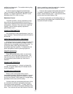
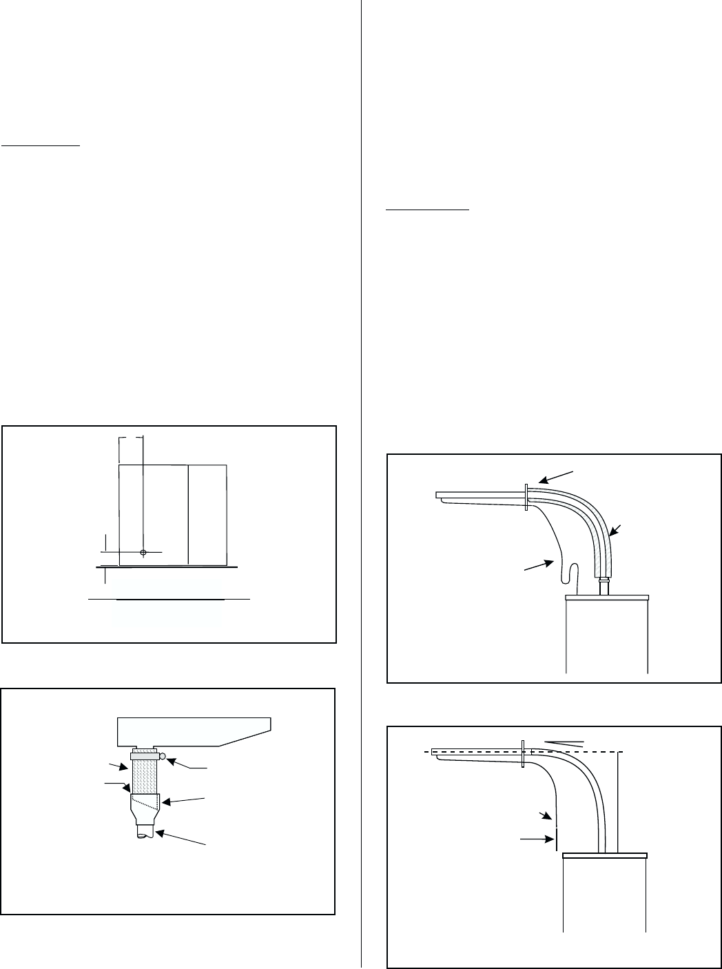
STEAM LINE
1.1. Steam lines for SGH models 010 through 020
require a minimum 7/8" O.D. (nominal 3/4")
copper pipe. For steam runs longer than 20 ft
use insulated nominal 1" copper to ensure the
draining of condensate.
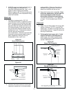
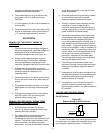
2. Field-supplied hard copper with ½" thick
snap-on insulation is recommended for
steam supply, with Liebert supplied steam
hose coupling used to make connection to
cylinder. See Figure #17.
-6-
FactorySupplied
Taperedcutis
recommended
3/4”Copper Pipe
(NotSupplied)
Copper Reducer
(11/4”-3/4”)To
Serve AsFunnel
Drain.Factory
supplied.
Air Gap
NOTE: Steam hose should not reach bottom of the funnel.
In the event the building drain is plugged this becomes an
overflow
p
oint.
ClampAnd
7/8"I.D.Hose
Figure #16
MODEL A in. (mm) B in. (Mm)
010-020 1.0 (25) 5.0 (127)
050-100 2.2 (55) 6.2 (158)
200 LEFT 2.2 (55) 6.2 (158)
200 RIGHT 2.2
(
55
)
19.6
(
498
)
A
Wall
Bottom View
B
Figure #15
Drain Line Connection
Trap
See Section On
Condensate
Return Line
Field Supplied
Insulated Hard
Copper Pipe
Or Flexible
Steam Hose
Available
From Factory
Clamp To Steam Distributor
Or Remote Blower Pack
Figure #17
Steam Line Connection
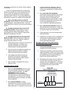
Min. 12"
Min. 10 Degree Slope
Trap
* See Section On
Condensate
Return Line
NOTE: Trap must be 3' minimum down from steam distributor.
If not, condensate must be routed to drain.
Figure #18
Sloping the Steam Line