


B-6
OPERATION
B-6
OUTBACK™ 145
¤
4. Insert the electrode into the electrode hold
er.
5. Set the current control dial to the desired output
current .
6. Start the gasoline engine.
See ENGINE OPERATION in this section of
the manual.
7. Strike an arc and begin welding.
AFTER YOU FINISH THE WELD:
1. Stop the gasoline engine. See ENGINE OPERA-
TION in this section of the manual.
2. Allow the electrode and work to cool completely.
3. Remove the work clamp from the work.
4. Remove any remaining piece of electrode from the
electrode holder.
5. If you are finished using the OUTBACK 145 for
welding, disconnect the welding cables from the
weld output terminals. Reattach the flange nuts and
leave them on the terminals.
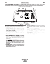
For DC+ welding, the electrode cable is to be connected
to the “+” output stud and work cable to the “-” output
stud. (For DC- welding, reverse these connections.)
Semi-automatic Wire Welding with a Lincoln Wire
Feeder/Welder
The
OUTBACK™ 145
generator power can be used to
supply up to 4250 watts continuous input power to a
Lincoln Wire Feeder/Welder. The Wire Feeder/ Welder is
equipped with all the supplies needed for Flux-Cored Arc
Welding (FCAW). Also some Wire Feeder/Welders come
equipped with the essentials needed for Gas Metal Arc
Welding (GMAW) or MIG processes, while others require
the purchase of a conversion kit. These products are
available where Lincoln products are sold. Contact your
local authorized Lincoln representative for more details.
Plasma Cutting with Lincoln Pro-Cut 25.
The
OUTBACK™ 145
generator power can be used to
supply up to 4250 watts continuous input power to a Pro-
Cut 25. The Pro-Cut will work satisfactorily under the fol-
lowing conditions:
1. Set the Current Control on the
OUTBACK™ 145
to
the 145 amp position. (Higher Settings may result in a
shutdown of the Pro-Cut 25.)
2. Leave the "ON/OFF" switch on the Pro-Cut "OFF"
until the
OUTBACK™ 145
has been started and is
at full operating speed.
WELDING OPERATION
The OUTBACK™ 145 can deliver from 50 to 145
amps of welding output current . Output can be
adjusted by setting the current control dial on the
output control panel.
You can get maximum welding output by setting the
dial to 145 AMPS. At high current settings like this,
some output may decrease as the machine is used.
If you are welding for a long time, you may need to
turn the dial slightly upward to maintain the same
results.
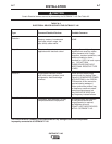
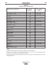
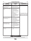
The numbers on the dial correspond to the approxi-
mate amps needed to weld using specific Lincoln
welding rods. Table B.2, WELDING APPLICATIONS,
give you the recommended dial settings based on the
thickness of the work and the size and type of rod
you’re using.
TO USE THE
OUTBACK™ 145
FOR WELDING:
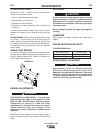
1. Remove the flange nuts from the weld output ter-
minals and place the work and electrode welding
cables over the terminals. See Figure B.1 and
B.1a. Replace and tighten the flange nuts
securely. Be sure the connections are tight.
2. Select the appropriate electrode. See Table B.2
3. Attach the work clamp securely to the work you are
welding.
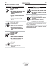
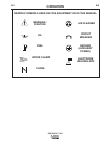
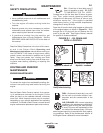
WARNING
ELECTRIC SHOCK can kill.
• Do not touch electrically live parts
or electrode with skin or wet cloth-
ing.
• Insulate yourself from work and
ground.
• Always wear dry insulating gloves.
MOVING PARTS can injure.
• Do not operate with doors open or
guards off.
• Stop engine before servicing.
• Keep away from moving parts.
Only qualified personnel should install, use, or
service this equipment.
ENGINE EXHAUST can kill.
• Use in open, well ventilated areas
or vent exhaust outside.
• Do not stack anything on or near
the engine.