


F-1
DIAGRAMS
F-1
OUTBACK™ 145
¤
L13929
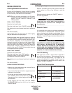
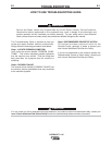
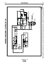
WIRING DIAGRAM - OUTBACK 145
_
WORK
6
5
3
CB1
20A
J6
9
7
+
-
ROTOR
FIELD
SLIP
RINGS
W2
W1
CB1
20A
6A
6B
GND-F
3B
3A
GND-D
3
GND-C
GROUND STUD ON
CONTROL PANEL FRONT
GND-E
_
+
D1
WORK
GND-H
GND-C
5 5A
5A
5B
5B
NEUTRAL STUD
ON CONTROL
PANEL BOTTOM
GND
GND
6A
SUPPRESSOR
ASSEMBLY
204
MODULE
LOW OIL
SWITCH
RUN/STOP
SWITCH
MAG
ENGINE WIRING
D3
(+)
(-)
C1
600 μFD
D2
HOUR
METER
(+)
(-)
205
202A
201A
205
200A
100 W
3.3
Ω
202B
OUTPUT
RHEOSTAT
201C
200
200C
201
(+)
(-)
9
7
201B
ENGINE
FOOT
GENERATOR
SUPPORT
FRAME
GROUND
201B
+
ELECTRODE
CHOKE
L1
EL-B
ELEC
SILVER
J4
SILVER
A.04
120 VAC
120 VAC
J5
240 VAC
203
202 202C
201D
NOTE: This diagram is for reference only. It may not be accurate for all machines covered by this manual. The specific diagram for a particular code is pasted inside
the machine on one of the enclosure panels. If the diagram is illegible, write to the Service Department for a replacement. Give the equipment code number.