


B-7
OPERATION
B-7
OUTBACK™ 145
¤
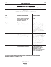
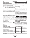
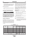
TABLE B.2
ELECTRODE SELECTION GUIDE
120V Receptacle Operation:
• Set the Output Control on the Pro-Cut 25 no higher
than the 15 amp position.( Higher settings may cause
circuit breaker on the
OUTBACK™ 145
to trip.)
• Maximum material thickness that can be cut is 1/4".
240V Receptacle Operation:
• The Pro-Cut 25 may be used for its full range of con-
trol.
• Maximum material thickness that can be cut is 3/8".
AUXILIARY POWER OPERATION
Be sure that any electrical equipment plugged into
the generator AC power receptacles can with-
stand a ±10% voltage and a ±5% frequency varia-
tion. Some electronic devices cannot be powered
by the OUTBACK™ 145 Refer to Table A.2, ELEC-
TRICAL DEVICE USE WITH THE OUTBACK™ 145,
in the INSTALLATION section of this manual.
-------------------------------------------------------------
GENERAL INFORMATION
The OUTBACK™ 145 is rated at 4750 Peak watts or
4250 continuous watts. It provides both 120 volt and
240 volt power. You can draw up to 20 amps from
either side of the 120 volt duplex receptacle, but not
more than 35.4 amps from both sides at once. Up to
17.7 amps can be drawn from the single 240 volt
receptacle.
WARNING
CURRENT RANGE (AMPS)
AWS ELECTRODE
CLASSIFICATION ELECTRODE TYPE POLARITY
3/32 SIZE 1/8 SIZE 5/32 SIZE
E6010 FLEETWELD® 5P DC+ 50-75 75-135 -
E6011 FLEETWELD® 35 DC+ 50-75 70-110 80-125
E6011 FLEETWELD® 180 DC+ 50-80 55-110 105-125
E6013 FLEETWELD® 37 DC± 70-95 100-135 -
E7018 EXCALIBUR® 7018 DC+ 70-100 90-125 125-145
E7018 JETWELD® LH-73 DC+ 65-85 90-125 -
E708-17 & E308L-17
BLUE MAX® 308/308L AC-DC
DC+ 50-80 75-110 80-125
ENi-CI SOFTWELD® 99Ni DC+ 50-80 80-110 -
- WEARSHIELD® ABR DC+ - 50-150 -
1/8 AND
SHEET THICKNESS THINNER 1/8 AND THICKER
Electrical loads in watts are calculated by multiplying
the voltage rating of the load by the number of amps
it draws. (This information is given on the load device
nameplate.) For example, a device rated 120 volts, 2
amps will need 240 watts of power (120 x 2 = 240).
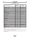
You can use Table B.3, AUXILIARY POWER APPLI-
CATIONS, to determine the wattage requirements of
the most common types of loads you can power with
the OUTBACK™ 145 Be sure to read the notes at the
bottom of the table.
TO USE THE OUTBACK 145 AS AN AUXILIARY
POWER SUPPLY:
1. Start the gasoline engine. See ENGINE OPERA-
TION in this section of the manual.
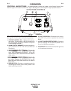
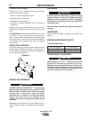
2. Set the current control dial on the output control
panel to “MAX.” See Figure B.1.
3. Plug the load(s) into the appropriate 120 volt or
240 volt power receptacle.
NOTE: During welding, the maximum generator out-
put for auxiliary loads is 100 watts.
NOTE: You can supply multiple loads as long as the
total load does not exceed 4750 Peak watts
or 4750 continuous watts. Be sure to start
the largest loads first.