


B-3
OPERATION
B-3
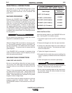
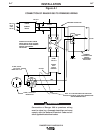
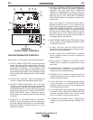
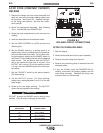
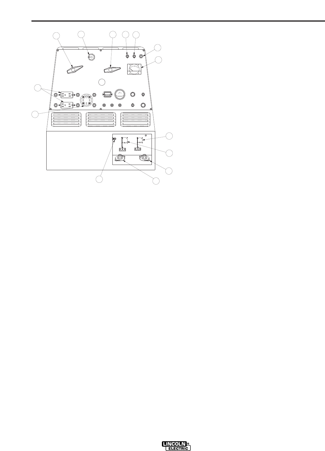
FIGURE B.1
OUTPUT PANEL CONTROLS
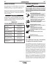
WELDER/GENERATOR CONTROLS
See Figure B.1 for the location of the following features:
1. OUTPUT RANGE SELECTOR: Selects continuous
current output for constant current stick or TIG appli-
cations (blue settings) and constant voltage wire feed
applications (red settings). The amperages on the
dial correspond to the maximum amperages for each
corresponding range setting. Never change the range
switch setting while welding since this could damage
the switch.
2. FINE OUTPUT CONTROL: Allows fine adjustment of
current or voltage within the selected output range.
3. POLARITY SWITCH: Selects DC+, DC- or AC weld-
ing output. Color codings aid in the proper selection
of stick (blue) or wire feed (red) polarity setting. On
the RANGER 300 DLX the color setting of the polarity
switch must match the color setting of the OUTPUT
RANGE SELECTOR. Never change the polarity
switch setting while welding since this could damage
the switch.
4. CONTROL AT WELDER/REMOTE CONTROL
SWITCH: Allows the operator to control welding out-
put at the welding control panel or at a remote station.
Remote connections are made at the 6 pin or 14 pin
amphenol connector.
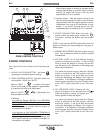
5. WELDING TERMINALS SWITCH (DLX Model Only)
The toggle switch labeled “WELDING TERMINALS
ALWAYS ON” and “WELDING TERMINALS
REMOTELY CONTROLLED” is used to control the
operation of the RANGER 300 DLX output contactor.
With the switch in the “WELDING TERMINALS
ALWAYS ON” position, the contactor is closed at low
and high idle.
When a wire feeder or TIG Module control cable is
attached to either the 6 pin of 14 pin amphenol con-
nector and the Welding Terminals switch is in the
“WELDING TERMINALS REMOTELY CONTROLLED”
position, the contactor is open in low idle and high idle
until and the wire feeder trigger or Amptrol is closed.
This closes the 2-4 circuit. When the gun trigger or
Amptrol is released, the contactor opens and there is
no voltage present at the electrode.
6. WIRE FEEDER POWER CIRCUIT BREAKER: Opens
the wire feeder circuit and disables the feeder if a fault
is detected in the circuit.
7. 15 AMP, 120 VOLT DUPLEX RECEPTACLES:
Connection point for supplying 120 volt power to oper-
ate one or two electrical devices.
8. 50 AMP, 120/240 VOLT RECEPTACLE: Connection
point for supplying 240 volt power to operate one
electrical device.
9. WELD OUTPUT TERMINAL (TO WORK) WITH
FLANGE NUT: Provides the connection point for the
work cable.
10. WELD OUTPUT TERMINAL (TO ELECTRODE
HOLDER) WITH FLANGE NUT: Provides the con-
nection point for the electrode holder.
11. GROUND STUD: Provides a connection point for
connecting the machine case to earth ground for the
safest grounding procedure.
12. 6 PIN AMPHENOL: For attaching optional remote
control equipment to the RANGER 300 D/DLX
(Includes contactor closure circuit on the Ranger 300
DLX & remote control circuit).
13. 14 PIN AMPHENOL (DLX Model Only): For attaching
wire feeder control cables to the RANGER 300 DLX
(Includes contractor closure circuit, remote control
circuit, wire feeder 115/42 volt power source).
14. VOLTMETER (DLX MODEL ONLY) - Displays actual
voltage at the output terminals when welding in CV-
mode.
RANGER 300 D AND 300 DLX
7
10
12
13
9
2
6
5
8
4
11
1
FE
3
14