


B-8
OPERATION
B-8
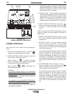
AC/DC STICK (CONSTANT CURRENT)
WELDING
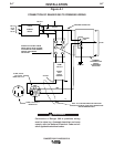
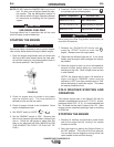
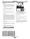
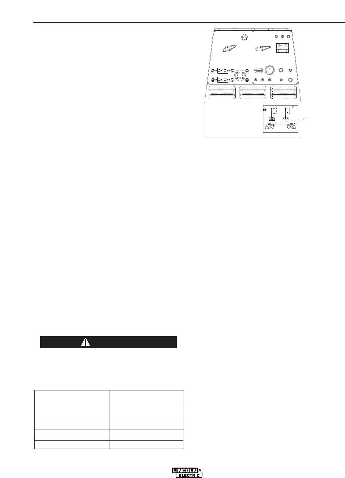
1. Remove the flange nuts from output terminals and
place the work and electrode welding cables over
the terminals. See Figure B.4. Replace and tight-
en the flange nuts securely. Be sure the connec-
tions are tight.
2. Select the appropriate electrode. See “Welding
Tips 1" included with your RANGER 300.
3. Attach the work clamp securely to the work you are
welding.
4. Insert the electrode into the electrode holder.
5. Set the IDLER CONTROL to AUTO and start the
diesel engine.
6. Set the RANGE switch to a setting equal to or
slightly lower than the welding current recommend-
ed for the electrode being used. For the best weld-
ing performance, always set the RANGE switch to
the lowest CC-blue setting that will give the desired
weld current. This will assure that the OUTPUT
dial is set towards the high end of the dial. If the
OUTPUT dial is set at 10 and the welding current
is to low, move the RANGE switch to the next high-
est setting.
7. Set the POLARITY switch to the desired polarity
(CC-blue setting).
8. Set the OUTPUT control. For stick welding,
always use a setting between 5 and 10 on the dial
(blue range).
9. Strike an arc and begin welding. The OUTPUT
control can be adjusted while welding.
DO NOT change the RANGE switch setting while
welding. This can result in damage to the switch.
------------------------------------------------------------------------
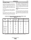
FIGURE B.4
WELDING CIRCUIT CONNECTIONS
AFTER YOU FINISH WELDING:
1. Stop the engine.
2. Allow the electrode and work to cool completely.
3. Remove the work clamp from the work.
4. Remove any remaining piece of electrode from the
electrode holder.
5. If you are finished using the RANGER 300 for
welding, disconnect the welding cables from the
weld output terminals. Reattach the flange nuts
and leave them on the terminals.
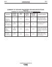
RANGER 300 D AND 300 DLX
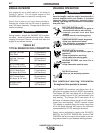
CAUTION
RANGE SETTING
ON MACHINE
ACTUAL
CURRENT RANGE
50
75
100
140
180
225
300
30 to 50 AMPS
50 to 75 AMPS
70 to 100 AMPS
95 to 140 AMPS
110 to 180 AMPS
130 to 225 AMPS
160 to 300 AMPS
FE
OUTPUT TERMINALS