


B-9
OPERATION
B-9
AC/DC TIG (CONSTANT CURRENT)
WELDING
1. Connect the K930-1 TIG Module to the RANGER 300.
Follow the installation instructions provided with the kit.
2. Refer to the instruction manual with the TIG module (IM
528) for operation with a RANGER 300. And proper
machine settings.
3. Set the RANGE switch to the appropriate setting for the
electrode you are using. Refer to IM-528 with the TIG
module or refer to Table B.2 for AC TIG welding.
4. Set the POLARITY SWITCH to the desired polarity.
5. Do not AC TIG weld on the 250 AC range setting. The
output current may exceed the rating of the RANGER
300.
6. Start the arc and begin welding.
NOTE: When using the RANGER 300 for AC TIG welding
of aluminum, the TIG Module is to be set for CON-
TINUOUS HF.
AFTER YOU FINISH WELDING:
1. Stop the engine.
2. Allow the electrode and work to cool completely.
3. Remove the work clamp from the work.
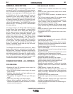
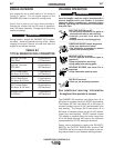
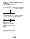
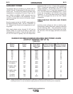
TABLE B.2
AC TIG WELDING
TIG ELECTRODE / RANGE SETTINGS
(1) The welding current will be approximately 200 amps with the range switch set at
120 and the OUTPUT CONTROL set at 10. Do not use a range setting higher
than 120 for AC TIG welding with a pure tungsten electrode.
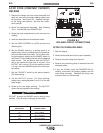
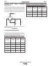
DC WIRE FEED WELDING (CV)
WITH RANGER 300 DLX
1. Connect one of the following: the LN-25, LN-7 or
LN-8 Wire Feeder.
2. Some recommended Innershield electrodes are:
.068 NR-211MP, .068 NR-232, NR-203 series,
5/64 NR-311, and 5/64 NS-3M also Lincore® 33
and 55 hardfacing electrodes can be used. Cable
length and other conditions can affect the ultimate
results of this application. Request Lincoln publi-
cation N-675 for additional information.
Recommended Outershield electrodes are .045
(1.1 mm), .052 (1.3 mm), and 1/16 (1.6 mm)
Outershield 71 and 1/16 (1.6 mm) Outershield 70.
Request Lincoln publication GS-200 for additional
information.
For MIG welding, the recommended electrodes are
.030 (0.8 mm), .035 (0.9 mm) and .045 (1.1 mm) L-
50 and L-56. You must use a blended shielding
gas such as C25 (75% Argon, 25% CO2 ).
Request Lincoln publication GS-100 for additional
information.
3. Set the IDLER CONTROL to “AUTO” for the LN-25
“HIGH” for the LN-7 or LN-8 and start the diesel
engine.
4. Set the RANGE switch to either HIGH, MEDIUM
HIGH, MEDIUM LOW, or LOW (CV-red) depend-
ing on your wire size and speed.
5. Set the POLARITY SWITCH to either WIRE FEED
DC+ or WIRE FEED DC (red), depending on the
electrode.
6. Set the OUTPUT control to a setting between 1
and 10 that gives the most stable arc for the appli-
cation. Try a higher RANGE switch setting if the
arc is unstable.
7. Strike an arc and begin welding. The OUTPUT
control can be adjusted while welding. DO NOT
change the RANGE switch setting while welding.
This can result in damage to the switch.
AFTER YOU FINISH WELDING:
1. Stop the engine.
2. Allow the work to cool completely.
3. Remove the work clamp from the work.
RANGER 300 D AND 300 DLX
Pure (EWP)
Tungsten Diameter
“Range”
Switch Settings
Appropriate
Welding Current
1/8”
3/32”
1/16”
75, 100 or 140
(1)
50, 75 or 100
50, 75 or 100
100 - 200 amps
50 - 100 amps
45 - 150 amps
1% Thoriated
Tungsten Diameter
“Range”
Switch Settings
Appropriate
Welding Current
1/8”
3/32”
1/16”
100, 140 or 180
50, 100 or 140
50 or 100
160 - 250 amps
100 - 180 amps
60 - 120 amps